
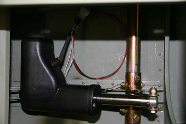
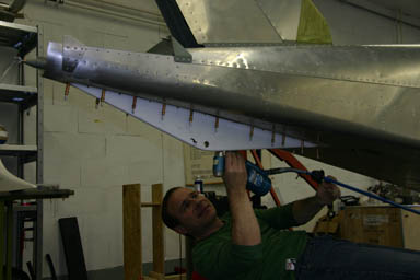
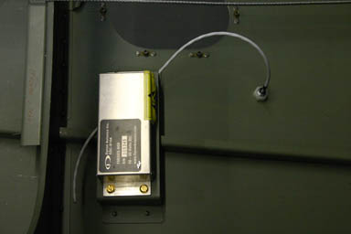
04.12.2008: Today I first finished installing the flap position sensor, as we now have the connectors for the wiring. There is a steel wire connecting the position sensor to the torsion arm to read the flap position, but unfortunately the wire was attached in a way that it made more movement than what the position sensor is designed for. To solve that I had to drill a new hole into the torsion arm. Nothing special, except in a very tight space.
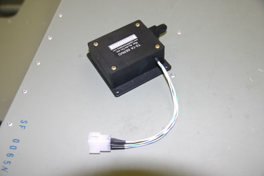
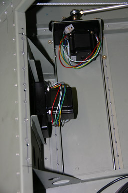
I then wired the elevator trim servo for installation.
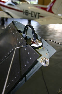
Next I started to install the tail skid.

Here a closer look.
Drilling all those holes into the fuselage meant that I had to vacuum the inside of the fuselage afterwards. Again quite a tight space to get into. I will definitely only close the fuselage top once every single remaining hole is drilled.
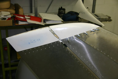
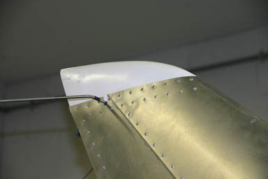
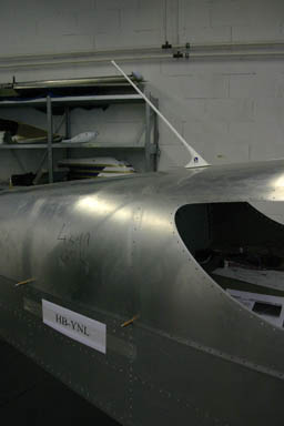
As the last item for today I finished installing the fin tip fairing. Inside will be VOR/GS antenna, which I received last week.
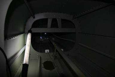
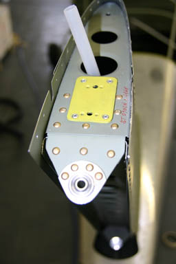
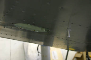
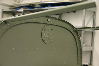
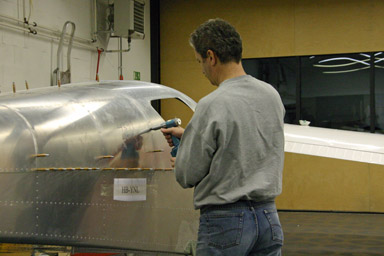
05.12.2008: Today I started with installing the transponder antenna. Here the antenna seen from the inside, with the paint removed around the two screws to ensure proper grounding.

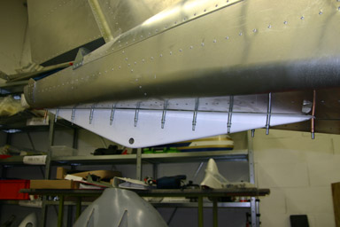
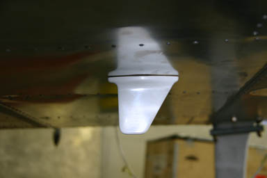
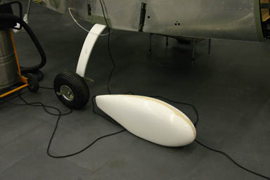
Below the antenna seen on the underside of the fuselage. I thought a plane with such elegant lines as the SportCruiser deserves something nicer than the normal “stick with the ball at the end” type antenna, so I chose a blade antenna. Of course it is a bit more expensive as the plain antenna, but it is good for 350 kts and 70’000 ft…
Rolf in the meantime continued with the tail skid. As the area underneath it is not ventilated nor has a drain we decided to apply primer to prevent corrosion in case some humidity enters into the tail skid.
Silvan also showed us how to seal the skid using the same type of sealant we used for the elevator.
Here Rolf sets the rivets, using Silvan’s new “chair” to work from underneath.
Next we installed the NAV antenna. We built a mounting plate…
then attached the antenna to it and ran the cable through the cable duct.
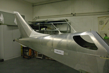
After installing the fin tip the whole thing looks quite professional. The rudder is missing on this picture.
I continued installing the Dynon autopilot servos. For the aileron servo we found a problem, as the new aileron mechanism which should give better balanced aileron and elevator forces, results in the aileron push rod being about 1.5 to 2 cm lower than with the original version. As a result the screw on the servo arm touches the aileron push rod. I will have to check with the factory what they recommend as fix.
In the morning I by the way went to see a member of our club who owns an automobile body shop very close to the airport, with a good size paint booth. He will let us paint our plane in there, so another problem solved. Another member of our club, who owns an aircraft restoration company, agreed to do the painting. We will do all the preparation work like cleaning, masking and sanding. The result should be an affordable paint job, but still of high quality.
06.12.2008: I went back to the airport to check for possible solutions for the servo problem described above. I found that I can easily lower the servo by up to 23 mm without getting into conflict with any other part of the structure. This solves the conflict and only requires drilling a few holes. I will check with CZAW whether they have already found that problem and what their modification is, or whether they approve my proposal.
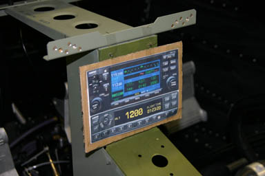
07.12.2008: I continued with the panel today, starting with drawings to get the panel cut. I will build a wooden sample first to make sure everything fits. All the avionics are ordered now, so our “little Airbus”, as some colleagues call it, will soon become reality.
I also updated the electrical consumer list to make sure the power consumption of the avionics stays within reasonable limits. The Dynons consume surprisingly little power, and the LED lights help too.
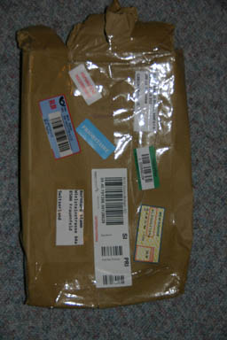
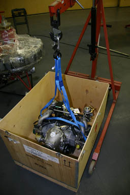
09.12.2008: Today I received the two missing engine mounting bars, great. I have to say that the support from the factory is excellent, I also got several mails from them regarding how to solve the autopilot issue. Below the bars, so installing the engine can start.
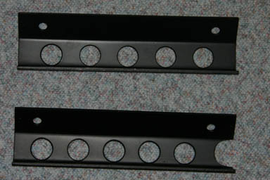
By the way, it’s impressive to see how many stamps and stickers are put on a parcel sent from the Czech Republic to Switzerland…
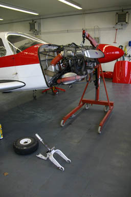
13.12.2008: Today I had a few hours at the airport so I thought I could try to fit the engine to the engine mount, but the “crane” was in use to repair the gear of the Cherokee of our club…
So instead I went over to Kuerzi, the avionics shop at our airport, to check whether our antennas had arrived. They had, so I could start fitting the COM antenna (Comant CI 121).
I also tried to solve the conflict between the autopilot servo arm and the aileron push rod, based on the information I received last week from CZAW. I did not have enough time to finish this, but from what I could see it seems to work now.
I will be on a business trip to Stockholm for nearly a week now, so not much progress until next weekend.
20.12.2008: Two weeks of holidays ahead of me, with hopefully some more time for building than during the previous weeks. I am still planning a first flight well into the first half of next year….
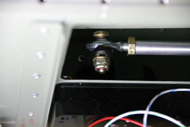
Today I first reinstalled the autopilot servos, using the middle hole a the servo arm as well as no washers to attach the connecting rod. That solved the conflict with the aileron pushrod.
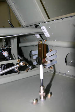
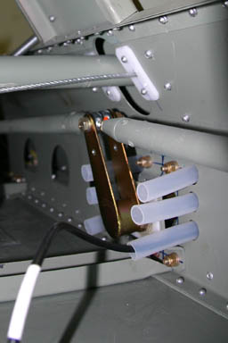
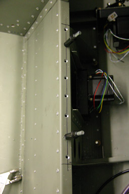
I then drilled the hole to attach the autopilot pushrod to the aileron mechanism. The six plastic tubes seen on the picture below serve as cable ducts from the space behind the seats through the center console to below the panel. To reduce electromagnetic interference’s I will use them as follows:
- Transponder antenna
- COM Antenna
- NAV Antenna
- Audio (headsets)
- NAV / strobe lights
- Electrics (flap motor, trim servo motors)
I also had a look how I have to modify the centre console to fit the Garmin GNS 430W and the GTX 330. They will just fit perfectly on top of each other with some millimeters clearance on top and below.
Finally the crane required to install the engine became available. We will have a building day tomorrow and I really want to see the engine on the engine mount by tomorrow evening.
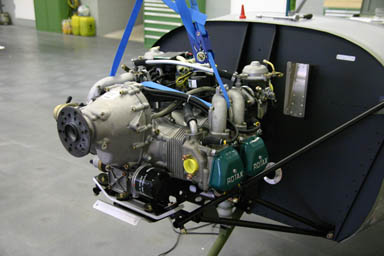
22.12.2008: We started today with installing the engine. Here it is! It still has the two mounts underneath which were used to fix it to the shipping crate.
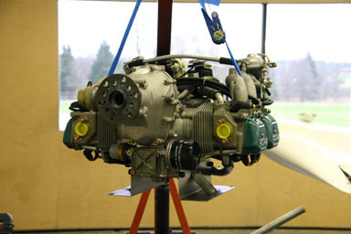
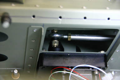
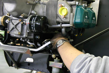
First we removed them and installed the two mounting bars which were missing in the kit, using the proper screws and a torque wrench.
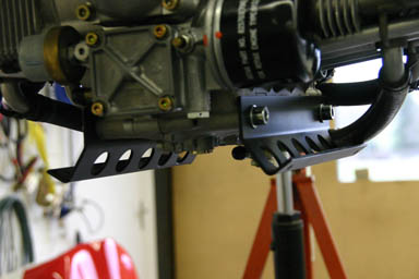
Then we lowered the engine onto the engine mount…
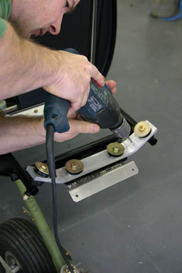
…and marked the holes to be drilled. Pretty tight work as can be seen below, we used the first five centimeters cut from a marker pen as described in the builder manual. Worked very well, except that I had red fingers afterwards from the leaking pen…
Rolf then drilled the holes…
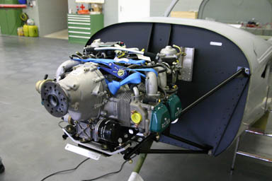
… so that we could finally install the engine permanently. All the holes fit perfectly, not bad. We had several visitors today, they were all surprised how much room there is around the engine. It nearly looks a little lost on the engine mount. The wide fuselage is an advantage here too.
Next I wanted to fit the cowling, but I have to check first how to install the Sensenich propeller.
After that I installed the outside air temperature (OAT) sensor. It connects to the Dynon remote compass sensor, which is convenient as they both are installed in the back of the fuselage and the cable from the sensor to the remote compass
can be kept very short.
Below the sensor seen from underneath the fuselage. In that location it is far away from the engine and not exposed to direct sunlight. The OAT sensor allows the Dynon to calculate true airspeed as well as density altitude and wind direction and speed (if connected to a GPS as well). The result is a small wind direction arrow in the lower right corner of the EFIS, just like in an Airbus.
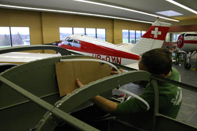
Rolf then started installing the soundproofing foam sheet on the rear wall of the cockpit. The foam we use is from Aircraft Spruce, part nr. 09-42725. It doesn’t cost much and meets FAR 25.853a flammability requirements. Rolf build cardboard templates before cutting the foam, which worked quite well. For gluing we used a contact adhesive which is good to 100o C (recommended by Silvan).
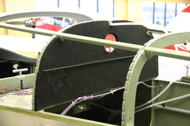
Below the result. It’s quite amazing the difference it makes if you knock on the back wall. No more of the rattling noise, which can be heard in some SportCruisers. The other surfaces of the back wall / luggage compartment will be covered with carpet, which has the same dampening effect, so we don’t need to cover them. We will however also cover the firewall on the cabin side. That part will be visible (even only if you creep underneath the panel), so we used the back wall as a training.
Rolf also drilled the holes in the access hatch in the back wall, which are used to let air escape from the cockpit into the fuselage. Ours did not have the holes, but the factory now makes them to reduce droughts in the cockpit. I took measures from one of the many photos I have from the SportCruiser of Urs.
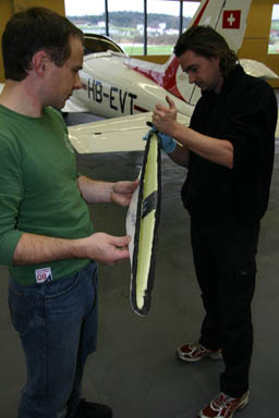
Next we unpacked the spats or wheel pants to fit them to the main gear legs. Drilling the holes is quite tricky, as the mountings are inside the pants and you can’t see them. We figured out however that with a strong lamp you can see them through the fiberglass.
I also went over to Kuerzi to check whether our remaining antennas had arrived. To my surprise they had already all the avionics except the ELT, which does not matter as it does not go into the panel. Like Christmas, just a few days too early…
The ELT had to be shipped surface mail, as it contains a battery and is therefore considered hazardous material. Why the hell is it FAA certificated to be installed in an aircraft, but can not be carried in one as cargo? The world is sometimes crazy… They got the ELT antenna however, and as I wanted it it has the same shape, colour and angle as the COM antenna, which will look cool…
With all the avionics and instruments at home I can now finish the panel layout. Another step forward.
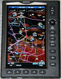
I only had a quick look into the Garmin GNS 430W and GTX 330 boxes to check whether everything was inside, but I did of course unpack and play with the GPSMAP 695. It has an unbelievably sharp and bright screen, and operates just about as my old black and white GPSMAP 196. Very intuitive and surely a great VFR tool. On Christmas we will go and visit family near Geneva, if my wife drives the car I can play with the GPS…
Kitfox Thomas asked me about my experience with Aircraft Spruce Europe. I had ordered my stuff (soundproofing sheet, OAT sensor and a few small pieces) on the 17th November, but even though it said “ready for shipment in 2 – 3 days” on the internet they non the less had to order some of the items from the US. I guess they only get a shipment once they have a sufficient back order, so they finally only sent out my order on the 10th December, which meant I got the parcel on the 19th, so about a month after ordering. I guess they have the more common parts on stock, so shipping should normally go faster. I had sent them an inquiry by e-mail on the 1st December to ask about the status of my order and received an answer within a few hours, so not bad. Also the prices are fully correct, and shipping is of course much, much, much cheaper (19 €) then when ordering from the US.
24.12.2008: Merry Christmas to all the readers of my building log.
26.12.2008: We just got back from visiting family near Geneva for two days. I let my wife drive a bigger part of the way so I could sit next to her and play with the GPSMAP 695 (she didn’t mind, really). It’s just easier to play with it in a moving vehicle than at home at the desk using the built in simulator. Just the ground proximity function can’t be tested in a car, as it says all the time “pull up, pull up”… The 695 is as intuitive to use as my old 196, just with a much, much bigger and better colour screen. At home I downloaded the tracks into the new version of MapSource, a utility provided by Garmin to store maps, waypoints, routes etc.. MapSource let’s you view the recorded tracks in Google Earth, the result is quite stunning. Below the route I recorded driving from the airport to my house.
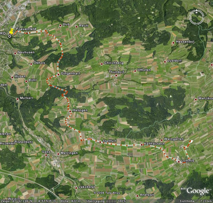
If you zoom in, all of the registered positions of the track are precisely on the road.
I started designing the centre panel with the GPSMAP 695 mounted in kind of a door that can be opened, giving access to a “glove box” to store maps, checklists, sandwiches and whatever one needs during a longer flight. The box will be around 17.5 cm wide, 20 cm high and 30 cm deep, which means quite some storage room. Everything is quite tight, however, so quite a tricky task. And of course it should look nice as well.
29.12.2008: Yesterday I started building two stands to place the wings on, as I want to work on them parallel to working on the fuselage. I am reusing the Styrofoam blocks on which the wings were placed during shipment, and I try to build them in a way that I can also use them to transport the wings on the roof of my car.
Today I first started with producing some bushings that I need to install the control rods from the autopilot servos to the control system. We ordered the autopilot servos directly from Dynon, as CZAW currently only sells the Digitrak autopilot, so we have to look for all the small bits our self. I am sure I could have asked CZAW to send the bushings to me, but I did not want to stretch their support too much so I decided to make them myself. I did not find the right diameter 4130 steel tube so I made them from a AN bolt (they bushings are only used as spacers, so this does not matter). I made them on the lathe in our maintenance shop. I have not worked with a lathe since my apprenticeship, which is 27 years ago, but it all came back within minutes.
Here a picture showing how I drilled the inner hole, and the final product before anti corrosion treatment.


I then decided to close the fuselage at least on the right side, as this will allow me to install the fairing between the upper fuselage and the fin and also the antennas. I will leave the fuselage open on the other side for as long as possible to still have easy access to the wring until it is all tested. Even though this took around 400 rivets I only needed about an hour to set all of them, using the pneumatic riveter (thanks again to Samuel to let me used it). I definitely know now why I am not building a Vans.
Below the result. I placed the antennas on top just to see how they fit. The front one (right) is the COM antenna, the left one is for the ELT. Also on the picture is the temporarily positioned fin fairing, which I will install tomorrow.
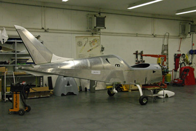
It slowly starts looking like an airplane…
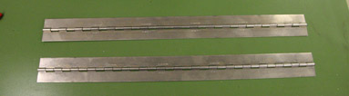
30.12.2008: With the bushings I made yesterday I finally had all parts to install the autopilot servos, which meant mainly riveting the brackets into the fuselage onto which the servos are mounted. When doing this I realised that the piano hinge, which holds the back of the pilot’s seat, would be installed over the rivet heads of the servo bracket. To solve this I decided to use flush rivets, which meant using sunk holes. Here how the holes looked after preparation.
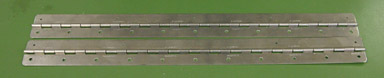
Below the hinges before and after drilling, There are eleven holes for rivets to hold the seat back as well as five holes for the screws which attach it to the fuselage. For the hinge which goes on the pilot side I had to space the holes so that they do not overlap with the rivets that hold the autopilot servo bracket.
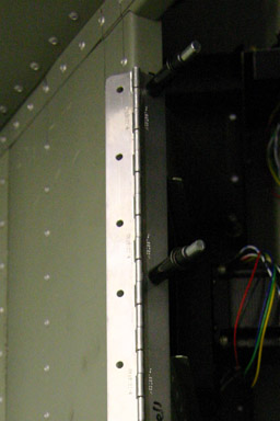
Below the flush rivets and three of the five holes for the screws, as well as the riveted servo brackets.
And here the same with the hinge fixed with clecos.
I also went over to Kuerzi to get some 2 mm aluminum sheet for building the extended panel which house the Dynons.
31.12.2008: Happy New Years Eve to everybody.