01.01.2009: I wish everybody all the best and a Happy New Year.
Let’s hope that this is going to be the year of the first flight of HB-YNL, and of many more flights with it of course. As Rolf and I are planning three full weeks of building during January and February this site will be updated quite frequently, so come back and check from time to time.
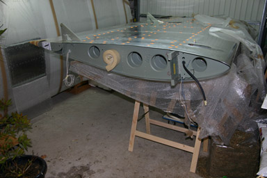
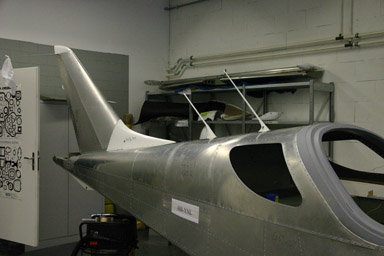
Today I finally finished the wing stands, so I was able to put the first wing onto them. It fills the garage quite well, luckily the fuselage is not in it anymore…
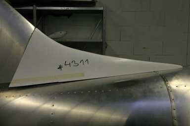
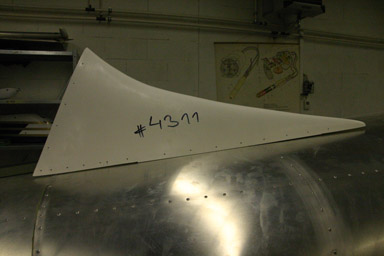
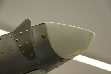
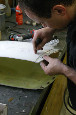
The orange stickers mark temporary rivets which have to be drilled out so that part of the wing skin can be removed. This will give access to the interior of the wing for the installation of the wiring (nav lights, strobes etc.) as well as the pitot system and the vapour return line. The composite wing tip has to be installed too, after that and a final inspection the wing can be closed. I need to finish the wings soon, as they have to go onto the fuselage to fit the wing fairings, as well as to set the elevator angle.
The pitot and the vapour return line are both in the left wing. I am starting with the right wing, so apart of the wing tip there is not much to do on this one.
03.01.2009: Today I finished the installation of the autopilot servos. That was finally quite a job. The I continued with the fuselage, for which I needed access to the interior of the back part. As the top skin is now permanently riveted on one side I had to find a way to lift the other side up.
To prevent the skin from getting bent I attached a wooden bar with clecos to the lower end. Like that I can easily lift it up with a rope, as can be seen on the picture below.
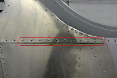
Then I finished attaching the skin on the already riveted side by adding the longer rivets required as per service letter SC-SL-001. The British sales agent realised that on the kits he imported the last eleven rivets on the lower row of the skin were too short (they go through two layers of skin, a stringer and an doubler to the stringer), so the standard rivets have to be replaced by longer ones. On my kit the skin was not yet installed, so I could just install the longer ones from the start.
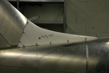
Then I started installing the fin fairing. Two stringers have to be riveted to the top of the fuselage first.
Then the fairing has to be trimmed to fit properly.
After that twenty holes have to be drilled per side. This sounds fairly easy, but special care has to be taken to drill the holes so that they do not overlap with the rivets that hold the fin. It took me about an hour to mark them correctly and to drill them.
Below the result after the usual sequence of drilling with small bit, attaching with silvery clecos, enlarging with bigger bit, attaching with bronce clecos, removing, deburring, re-attaching… I am getting quite some routine with that…
Last I started preparing the installation of the COM and ELT antennas. I had to drill out some rivets and replace them with flush ones, as my antennas seem to have bigger base plates than the ones used by the factory. I then also realised that the base of the antennas will be accross the skin joint. This would result in the the antenna not being orthogonal to the skin, so I prepared spacers to be put under the half of the antenna that sits on the lower skin.
04.01.2009: I started today with finishing the installation of the fin fairing. In addition to riveting it, I again used sealant to prevent water from getting underneath.
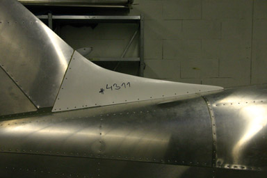
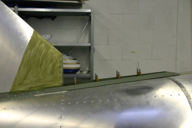
After that I installed the antennas. Thanks to the spacers I prepared yesterday they turned out to be perfectly vertical. If you look closely you can see the COM antenna and the shorter ELT antenna behind it in front of the fin.
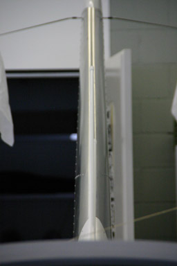
Here the antennas and the fin fairing seen from the side.
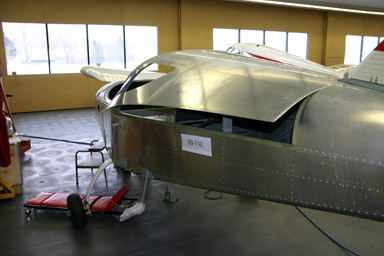
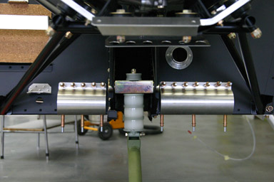
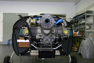
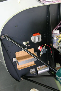
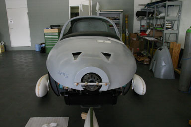
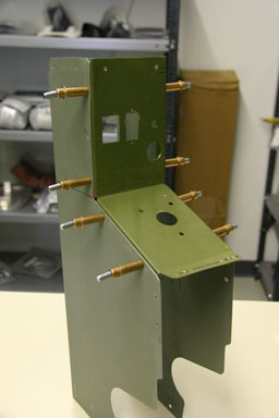
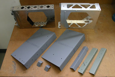
After that I turned my attention to the part of the plane forward of the firewall. First I installed the two bottom shrouds. They are riveted to the firewall and then bent backwards to the bottom of the fuselage.
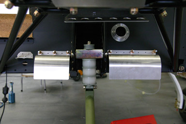
The result looks like that. I will not rivet them permanently, as I want to paint the fuselage fist.
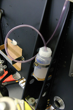
Then I started installing the engine accessories by following the instructions in the SportCruiser assembly manual step by step. First goes in the coolant water bottle,…
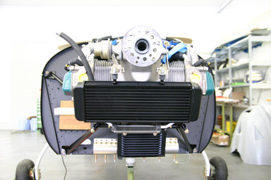
then follows the oil cooler…
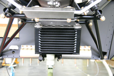
…then a first section of the oil hoses…
and then the water radiator. The instructions are quite well thought off, as the installed radiator would make it difficult to install the above mentioned section of oil hose.
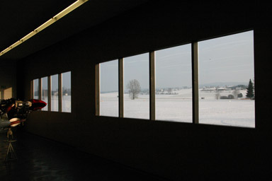
Later in the afternoon the fog suddenly disappeared. Below the view from the maintenance shop across the runway of our airport. I was really tempted to get one of the club’s planes out of the hangar and to go flying, but there was snow on the runway so I decided to continue building. It is non the less nice to build in a “room with a view”…
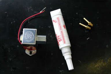
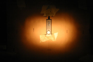
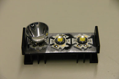
04.01.2009: Yesterday we received samples of the 10 W LED’s we want to use to build our landing lights and strobe lights (Seoul Z-Power LED P7 Series). They produce 90 lm per Watt, compared to the 15 lm/W of ordinary light bulbs and maybe 20 lm/W of halogen lamps.
The LED’s radiate through a 120o angle, but small reflectors are available with different beam angles. The ones below have a diameter of 28 mm and a beam angle of 12o.
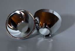
Today we made the first measurements with them. They are unbelievably bright, so you best wear those “men in black” sunglasses while measuring….
One LED with a 20o reflector is at five meters distance as bright as a 35 W Halogen lamp I used for comparison, but due to the smaller size it looks brighter. The 12o reflector results in a beam which is about five times brighter. We will probably install two LED’s per wingtip, which should be more than enough.
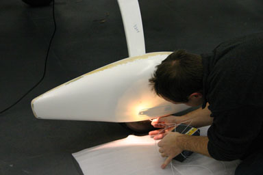
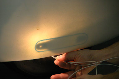
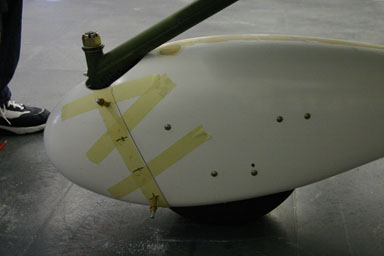
I also had a look a the wingtip to figure out how to install the landing lights as well as the NAV lights and strobes. For the landing light I figured out that it will probably be easier to install them in the aluminum part of the outer wing, as the wingtip leading edge curves back without a sufficiently long straight section.
09.01.2009: Today I received the 406 MHz ELT, which means the avionics are now complete. Getting the ELT is one of those ridiculous stories where safety rules have gone too far. All the other avionics arrived by regular air freight in December, but the ELT had to be shipped as hazardous cargo as it contains a battery. But the same ELT is certificated to be installed in passenger aircraft…
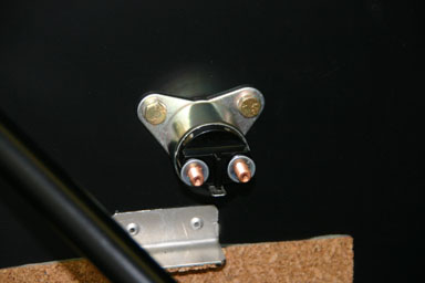
11.01.2009: I continued installing the engine accessories today. First the starter relay (or solenoid)…
…then the fuel pump, where I had to install the adapters first. I used Loctite 577 to seal the adapters, which is the same as Loctite 565 (which is recommended by CZAW) except that it is also suitable for stainless steel fittings.
Here the fuel pump installed on the firewall.
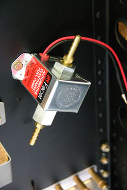
Finally I installed the rectifier (the one with the orange connector). I had to check on the pictures Sandro took at the factory to find the right location, as the two holes that can be seen above the rectifier did not seem right to me.
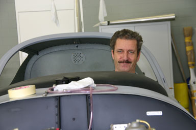
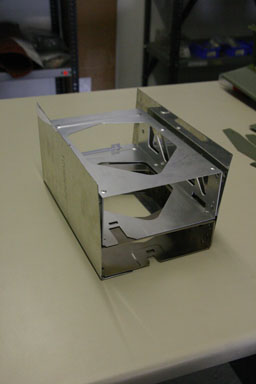
After that I build a cardboard template of the “glove compartment” I want to build behind the centre section of the panel, just to see how bit I can make it. To do that I had to temporarily install the glare shield.
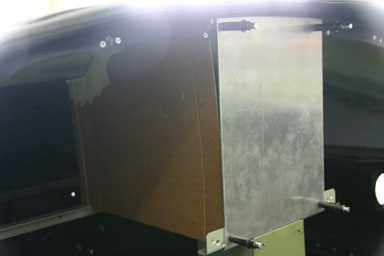
While doing this my younger daughter, who helped me today with building, took a picture of me sitting in the cockpit. I hope I soon have this perspective in flight..
Finally we went to the hangar to measure the beam angle and brightness of the landing and taxi lights on one of the Robin DR-400 of the club. The landing light produces a spot of about 40 cm width at a distance of 2 m, which means it has an opening angel of about 10o.
The taxi light has a clearly wider angle, probably around 15 to 20o.
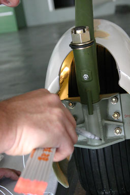
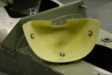
12.01.2009: Today we started installing the gear spats. The problem with them is that the fixtures, to which they are mounted, are inside the spats, so you can’t see from outside where to drill the holes for the mounting screws. Rolf came up with the idea to put a lamp into the spat so you can see where the mountings are. Last time we tried with one of Silvan’s LED working lights, but they are way too big. So today Rolf brought a 12 V halogen bulb, which we could easily stick into the spats. The result looks like that:
..or in more detail like that.
Cool, nearly like an X-ray. You just have to be careful as the bulb gets pretty hot, so it could easily burn the tire.
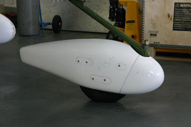
The result of our effort were two nicely mounted main wheel spats within no time.
The one on the front wheel gave some work, as it is made of two parts, and mounted in a different way.
Some of the mountings are very far back from the front, so we had to mount the halogen lamp on a stick to reach that far back.
Finally however we also managed to fit the front spat properly. We still have do mount the fittings to attach the front part, but that can wait until tomorrow.
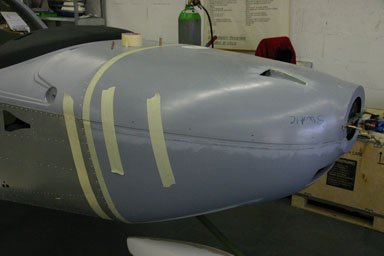
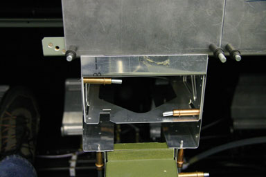
Next we started with the engine cowling. There are detailed instructions in the builders manual on how to mount and trim it so that it fits nicely, but unfortunately that depends on the propeller you are using. According to the builders manual the front of the cowling has to be 16 mm in front of the propeller flange, so that the spinner ends up with the proper spacing in front of the cowling, but that’s for the Woodcomp prop. The Sensenich propeller came with two different flanges, and after careful checking I concluded that none of them would give us the right clearance if we use the same distance to the propeller flange. I then called CZAW to check, but the have not used many Sensenich props so far, so Chip could not really tell me which one to use. He just confirmed that the spinner should have about one centimeter clearance to the cowling and we agreed that we would mount the cowling accordingly.
To mount the cowling a temporary mounting bar has to be installed at the distance mentioned above in front of the propeller flange.
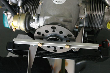
Then the cowling is attached to the back of that mounting bar with two clecos. After that the back of the cowling can be trimmed to the right length. We will do that tomorrow.
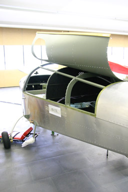
Rolf had to leave early and mounting the cowling alone is quite difficult due to it’s size, so I turned my attention to the back end of the plane. A small composite tailcone is used there to conceal the elevator horn. It is fixed with screws, not rivets, that go into nutplates, so that it can be removed for inspections.
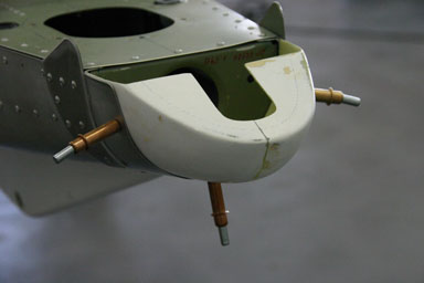
I installed the nutplates with small solid rivets…
…so that they are flush with the surface of the tailcone.
Here the tailcone installed.
I also had a lengthy discussion with Silvan on how to widen the centre console to install the Garmin’s, as I want to start building it tomorrow.
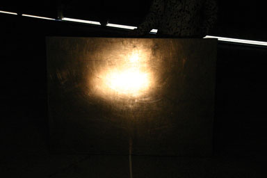
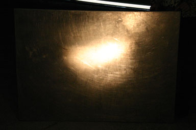
13.01.2009: We set up a small “optical lab” in one of the windowless rooms at the airport today to do some more detailed measurements with the LED’s and with ordinary landing lights. The following two pictures show the light pattern generated in about two meter distance by
a) a 100 W GE landing light as used in the Piper and Robin aircraft and
b) a single P7 LED. The 100 W landing light is of course significantly brighter, but also much more focused.
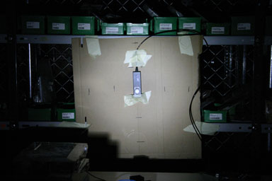
After that we did a test by looking at the lights from a distance of 15 m. We found that on the centreline the GE landing light is again definitely brighter, but at 1.5 m from the centreline the LED is significantly brighter than the bulb. The GE landing light has therefore a beam of about 10o horizontally and 6o vertically, which confirms my previous measurements, whilst the one of the LED is at least 25o. The lens we are using should achieve 12o according to the data sheet, which is therefore wrong. Our conclusion is that we will build a landing light into each wingtip made of three LED’s per light, which roughly gives us the brightness of the GE bulb, but with a wider beam angle.
After that I spent some time wirelocking some of the screws I have not done yet.
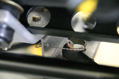
I then got some feedback from CZAW regarding propeller installation. To verify this we installed the propeller and then checked the clearance between the spinner and the cowling. The result is about 6 mm, which is on the lower end but still ok.

As the propeller was already installed we could also test the ground adjusting mechanism. It’s very easy, just loosen the six screws on the hub, twist the blades to the pitch wanted (there is a scale on the hub) and tighten the screws again. The two blades twist synchronously, so no measurement of blade angles necessary.

We then continued with fitting the cowling. The upper part was easy, but we struggled quite a bit with the lower part. The right side was ok,…
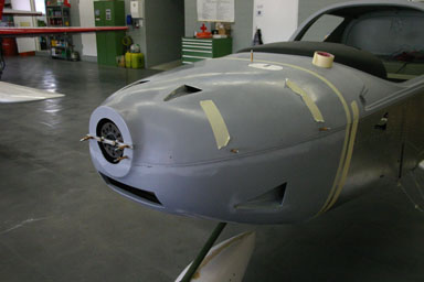
…but on the left side the overlap was about two centimetres too short. We found that the lip on which the cowling lies around the firewall was bent outwards instead of inwards, which probably makes the difference. We asked Silvan what to do and he told us he would bring us the following day a “tool” to solve that.
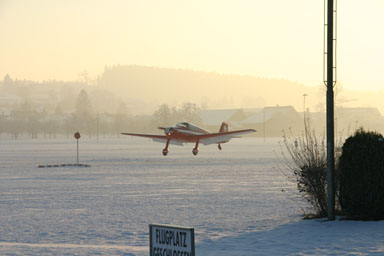
Just to tease us one of the club’s members got his Bölkow BO 208C out of the hangar to go flying. Even though the panel says airport closed he got the permission to try it. There is still about 10 cm of snow on our grass runway, but the ground underneath is well frozen (we had -13o last night). It worked perfectly.
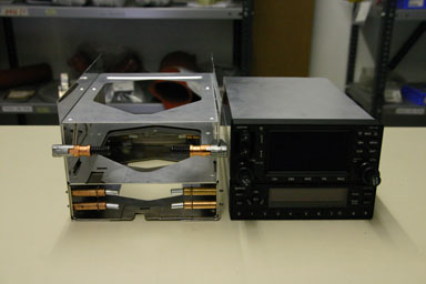
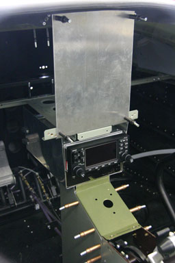
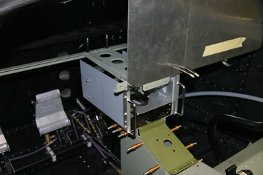
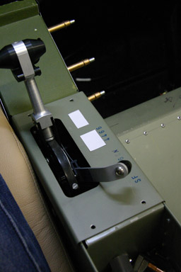
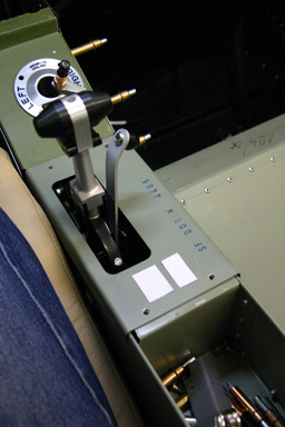
14.01.2009: Rolf could not come building today, so I started with the centre console. Below again the “problem description”. Our panel has to house the new Garmin 695, which does not leave enough room for the radio and the transponder. We could have fitted two Becker units in the centre console, where the flap switch is normally located, but we want two Garmins which are too wide.
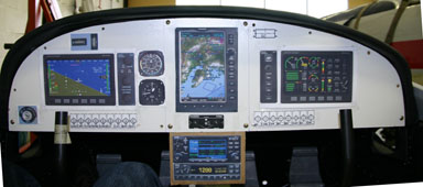
Here the same view, with the “real” panel installed, not the “cardboard and colour inkjet” version from the picture above.
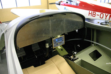
Below the centre console, when removed from the cockpit.
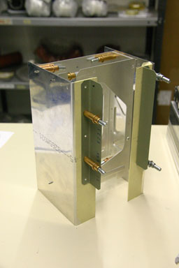
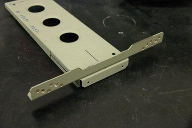
After quite some thinking and trying I designed a sturdy and light box around the Garmin mounting trays that could sit on top of a shortened centre console. The problem is that the whole thing has to be very sturdy, as it does have to support the weight of the two Garmins, and also of the panel above. The first step of building the box consists of producing two angles who wrap around the Garmin supplied mounting trays.
Then I shortened the two sides of the centre console…
…which then looks as can be seen below (compare with the picture of the console above).

Here the “box” next to the two Garmins it will house…
…and here a trial fitting. Even if the throttle is in the fully forward position it does not interfere with either operating or looking at the Garmins. The hand can even rest on the throttle while operating the radio, which can be convenient in bumpy weather. If the throttle is in the idle position both units can be removed from the trays.
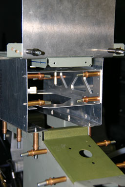
I then used two angles, which are normally used to attach the avionics racks to the panel above, to attach my “box” to the centre console.
The result is a very light and sturdy structure that can probably withstand 20g. Tomorrow I will still add two brackets to attach it to the top part of the panel, as well as add two protecting angles left and right of the radio so that one doesn’t to hit the dials with the knee when entering the cockpit.
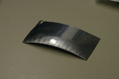
During lunch break Silvan suddenly came up with a “monster” of a tool. It can be used to “compress” sheet metal (the opposite of stretching it) to create curvatures. I have to admit I did not know something like that exists, even less do I know what it is called in English (maybe a reader of this page can help…). It only weights about a ton, which makes it very easy to use… Normally the tool is attached to a bench and the piece to be bent is brought to the tool, not the other way round.
Here a sample, where the front 2 cm of a flat piece of aluminum has been compressed, creating a nicely curved piece.
We then tried the “monster” on the cowling supporting lip, with the result that it really is curved more inwards than before. Tomorrow we will try to fit the cowling again to see whether our “problem” is solved now.
15.01.2009: One more full day of building today. Rolf started with finishing fitting the front half of the front wheel spat. It was quite a struggle, as the composite part had to be trimmed first, so it took him more ore less the whole morning.
He also hat to install all the nutplates, as the front half of the spat has to be removable.
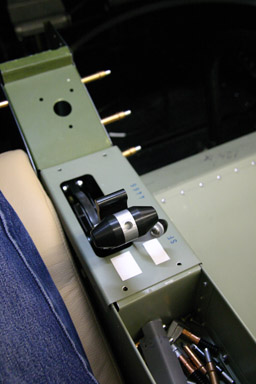
I continued with the avionics rack. I had to make an aluminum angle to close the gap between the radio and the upper panel. I also decided to install two handles (the ones used on 19″ housings) to the left and right of the radio so not to bump with the foot or knee against the frequency selector knob of the GNS430 when entering the cockpit.
Here the parts of my design after priming. I used a primer which also serves as a filler, as some of the parts will later be painted and will be visible when sitting in the cockpit.
To assemble the parts I needed some 6-32 screws as specified in the Garmin installation manual. They are not part of the installation kit, but with Kuerzi next door the problem was quickly solved.
Rolf and I then continued designing our various LED lights. Below the prototype of the landing light, with three LED’s but only one reflector (we first have to order some more). We installed the LED’s on a standard heat sink of which we trimmed some of the cooling fins to make room for the LED’s. The whole assembly will be closed by a kind of lid that holds the reflectors in place. Power consumption will be about 15 W, compared to the 100 W of a standard GE landing light bulb.
19.01.2009: I have spent a longer weekend in the south of France, so no progress with building. Today we had another look at the strobes design, we are still trying to figure out how many LED’s we need. The specification of the requirements in FAR 23 are not really clear.
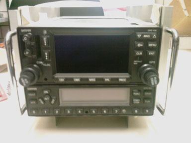
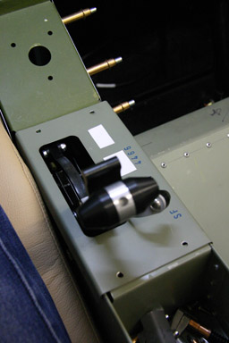
24.01.2009: After three days in Brussels I finally managed today to spend two hours at the airport. I continued working on the centre console by adding the handles, which I install to protect the knobs of the Garmin GNS430. I had to make two aluminum angles to which the handles will be fixed.
Unfortunately I forgot my camera at home, so I had to take pictures with my mobile phone. Here a side view:
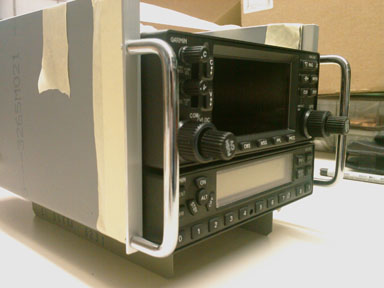
and here a view from the front.
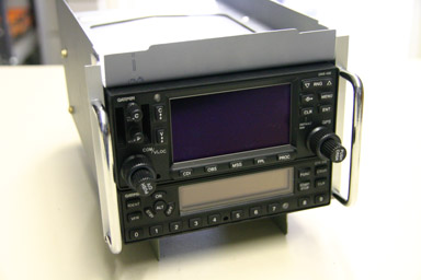
25.01.2009: I spent a few more hours today on the centre console. It’s amazing how much time it takes if you don’t just follow the assembly manual but start designing something yourself. Below the avionics rack in it’s assembled form.
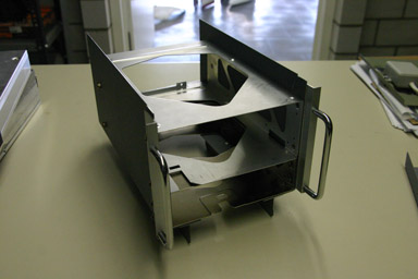
And this is what it will look like with the Garmins inside.
I started installing the rack in the fuselage, for which I had to design and manufacture some additional supporting brackets. After all the rack carries around 4.5 kg, which are 22.5 kg at 5 g…
I checked whether my calculations were correct so that I can still remove the transponder over the fuel selector valve, and luckily they were.
26.01.2009: I continued today where I stopped yesterday. I had to cut a bit of the centre support in order to make room for a filler piece between the centre section of the panel and the radios. After all I want it to look nice….
I then had a look where the flap switch and the flap indicator could go, as the radio and transponder took their space. Here some of the version I am considering. The switch has to be easy to reach when taking the hand from the throttle, and the indicator should be visible at all power setting.
All pictures are take from about where the eyes of the pilot are.
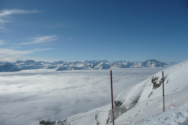
28./29.01.2009: Instead of “I’d rather go building” I went for “I’d rather go skiing” on Wednesday this week, so instead of some building pictures below a view from the Chäserrugg, which is a skiing area only about 60km by road from where we live. It’s great to get out of the clouds and into the sun once in a while, and thanks to the mountains that’s possible even when flying is not possible.
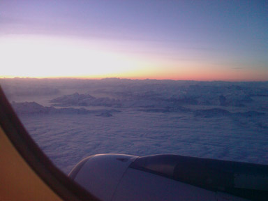
On Thursday/Friday I had to go to Vienna, and here a picture I took with my mobile phone shortly after takeoff from Zurich. It shows the mountain chain to which the Chäserrugg belongs where we went skiing yesterday.