02.09.2008: I’m busy drawing schematics. Things are turning out to be a little more complicated than I thought, as I want to do a few things differently than the way they are foreseen in the kit. This is not to criticize the kit, all material supplied is of good quality, but I am an electrical engineer…
For example, I evaluated a more professional type of connector, rather than the Faston type ones, and I’m adding a few more connectors to be able to quickly disconnect sections of the panel. I am also evaluating more modern looking switches, which means I have to have more circuit breakers, as some of the supplied switches have integrated circuit breakers and the more modern ones don’t… And then there are the LED nav lights, landing lights and strobes…
Today I also received the prices for the avionics, I might have to rethink some of my “dreams”…
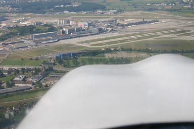
05.09.2008: I had a busy week, including a business trip to Berlin, but on Friday I went flying with Markus, who works in the same company and flies in the same club. We had planned since a while to make a “tour de suisse”, flying to a number of nice airfields, but never found the time until now. We started off in Lommis in one of the club’s Robin DR-400. First we had to cross the CTR of Zurich Airport. I always like doing that as you cross the airport at approximately 1000 ft AGL, which gives you a nice view. The picture below is from a previous flight
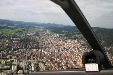
We then flew to Fricktal Schupfart and from there to Les Eplatures, which lies between the towns of La Chaux-de-Fonds and Le Locle. The runway starts just after the city, which results in a spectacular final approach across “downtown”. You just pray not to have an engine failure…
From Les Eplatures we flew to Lausanne, where the airfield is located on the hill above the city.
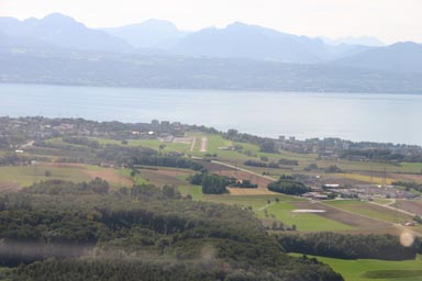
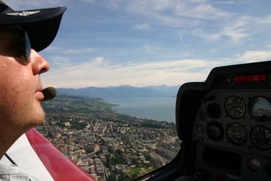
You don’t see the city when approaching from the north, as the terrain drops around 800 ft just after the runway, and the city lies on that slope. The runway slopes downwards for about 50 ft when landing from the north, as seen on the picture, so you better cross the threshold at the minimum speed and height. Taking off towards the south is quite spectacular, as you are quickly 1000 ft above ground even without climbing much. Below a picture taken just after taking off, with the city to the left.
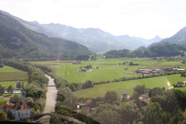
From Lausanne we continued to Gruyere, which lies nestled between some nice hills. The runway is just to the right of the river. Taking off is quite tricky when fully loaded, as you have to turn right just after take off not to hit the hill.
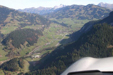
From Gruyere we continued to Saanen, which lies next to the famous skiing resort of Gstaad. The picture below is from a previous flight, taken at the beginning of the downwind leg. The downwind is 1’700 ft above the airfield, so you have to turn right into the valley just after the runway, then fly around Gstaad to loose height and then come back into the valley with the airport. This is a former Swiss Air Force base, from where they flew with jets until not too many years ago.
From Saanen we flew back to Lommis with a stop at Buttwil. On the way we passed the famous Eiger, Mönch and Jungfrau mountains…

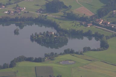
…and what I would call the ultimate dream home (the small castle on the island). Imagine, docking your Beaver floatplane next to your castle…
07.09.2008: I continued looking at the avionics issue today…
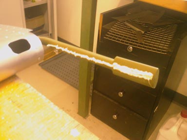
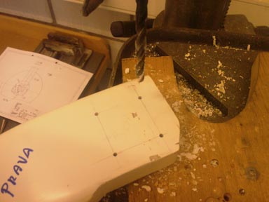
11.09.2008: Still no decision on the avionics side, so I continued with some other issues. First I marked the gear legs to drill the holes for mounting the wheels. One day, the SportCruiser will have to stand on it’s own feet…
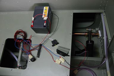
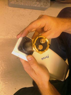
Then I temporarily hooked up the flap motor, flap position sensor and flap position indicator to make sure that I drill the holes for the sensor at the right location. Everything worked fine, but before I install the sensor permanently I have to order the connectors for the electrical system…
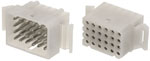
CZAW uses 6.3 mm AMP FASTON connectors, like in cars, which I do not really like, so I decided to use TYCO/AMP Square Grid connectors instead. We use them at work for products which are installed on-board trains or along railway lines, which means they are designed for even harsher environments than in planes. They are lightweight non the less, and use crimped pins. In addition they are available in anything from 4 to 36 pins, so I can use only one type of connector for just about anything. And that means also only one crimping tool… Pins are available for AWG 30 to 14, which should cover just about any application.
14.09.2008: I have been busy writing a CAME (Continuing Airworthiness Management Exposition) for our flying club, as well as updating the MOE (Maintenance Organisation Exposition) of the club’s EASA-145 certificated maintenance organisation. I have forwarded both documents to the Swiss Federal Office of Civil Aviation now, so I can concentrate again on my project.
Regarding avionics I wrote a mail to Becker Avionics, asking when they will come out with an 8.33 kHz capable radio, and to my surprise they sent me back a product announcement. It can be found in the documents section for those who are interested. At least there is now an alternative to Filser (which I don’t like) and the Garmin 430 (which I do like, but which is too expensive). I am still considering installing a Garmin SL30, as this would give me a VOR.
18.09.2008: Another day of building. Unfortunately I forgot to take my camera along, so all pictures are taken with the camera of my mobile phone.
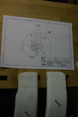
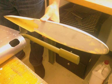
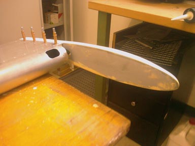
We started with correcting a “problem” we found with the elevator. As I mentioned earlier the elevator of the quick build kits is normally built by the factory, so the building of it is not described in the assembly manual. As we had to build the elevator our self we more or less had to interpret the drawings and to figure out how and in which sequence to assemble it. After we had finished we left it at the maintenance shop of our flying club and one day Silvan, the chief mechanic of the club, had a look at it. He noticed that composite tips can excercise quite some force onto the skin to which they are attached. I checked with other builders how their elevators are built and they told me that the tips seem not only to be attached to the skin but also to the mass balances, which are inside the tips. I then sent a mail to CZAW asking what to do and they confirmed that the composite tips are are glued to the mass balances using a polyurethane sealant.
The result of all of this is that we drilled out all the rivets holding the composite tips to remove them, checked that they are properly aligned with the mass balances and glued them as instructed.
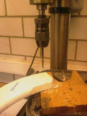
After that we started assembling the main landing gear. I had already marked the holes to be drilled some days ago, so after double checking by Rolf we started drilling.
The drilling went very well, using ordinary drills for metal.
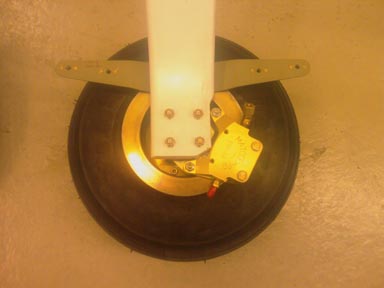
After that the same try and error procedure had to be applied as for the rudder, as the main gear is normally also built at the factory.
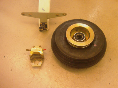
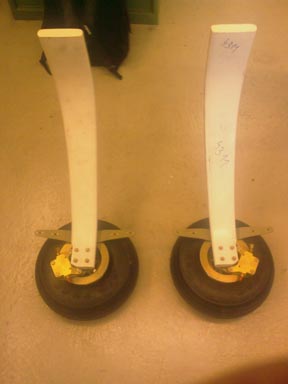
Finally we managed to find the right way, however, and the result was two nicely assembled gear legs.
19.09.2008: I just went quickly to check the elevator we did yesterday. The composite covers are now as “solid as a rock”, great. I then spent the afternoon drawing the schematics to figure our how many connectors and switches we have to order. We finally decided to use Molex Type 1625 / 3191connectors.
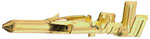
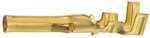
The reasons for this are that they are:
- available with gold plated contacts,
- in crimping and soldering versions,
- from 2 to 24 pins,
- for AWG 18 – 24 (type 1625) as well as AWG 14 – 20 (type 3191),
- can carry 5 A and 12 A respectively.
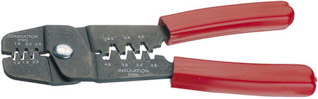
Most other types of connectors we had a look at are either not suited for thin wires, not available with gold plated contacts or have crimping tools that cost from 600 US$ upwards. The tool for the selected connectors costs only around 120 US$, and using a proper tool is a must for two electrical engineers….
20.09.2008: Yesterday I found an excellent building log on the web. It’s run by a British RV-7 builder, Richard Horan. Highly recommended.
I also found a page with a lot of information on the layout of electrical systems in planes under http://www.aeroelectric.com/. Just brows through “downloadable reference materials”, you can find information on just about anything there.
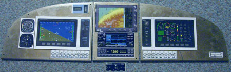
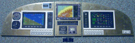
29.09.2008: I have just spent a week in Berlin at Innotrans, the worlds largest exhibition on Rail Transport and Technology, so no progress with building. Today I started with the final layout of the panel, using the real panel sections. I still have two options I am considering, with either the SL-30 NAV/COM plus Becker 8.33 kHz Radio and Becker Transponder or the GNS430W, with the Garmin transponder. Both give me a VOR as well as an 8.33 kHz radio. I had to realise that the space underneath the Dynon is not high enough to put the airspeed indicator and altimeter there, so I will have to move them to the left.