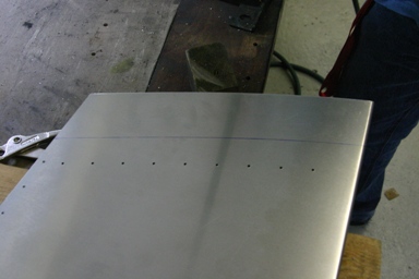
03.06.2008: Yeah, today we started building our SportCruiser!
Last Friday our project advisor visited me for the project kickoff meeting. We had to go through a six page checklist produced by the Swiss Experimental Aviation Association (EAS). The whole building has to be done and documented according to a process developed by them and approved by the Swiss Federal Office of Civil Aviation (FOCA).
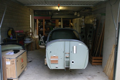
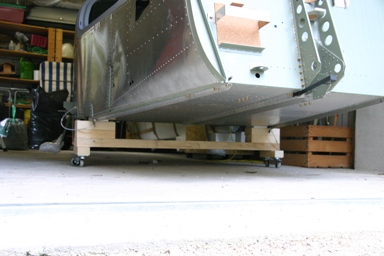
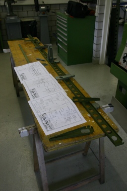
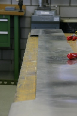
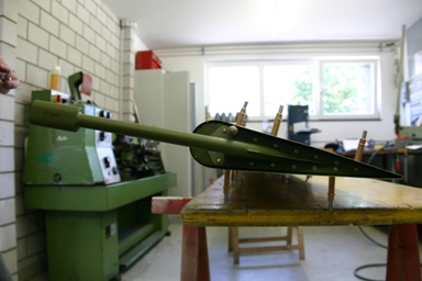
Over the weekend I prepared the workshop. First I had to put order, then I installed two additional lamps for better lighting. And finally I finished the trolley on which the fuselage rests so that I can move it around for better access (the workshop isn’t too big…).
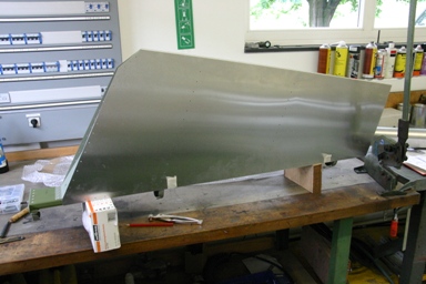
Here a picture of the workshop.
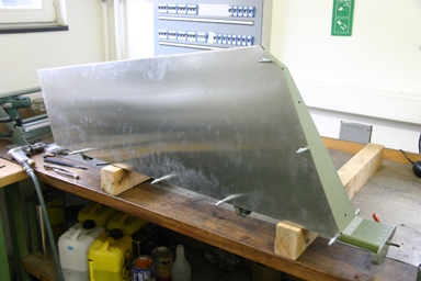
and here one of the trolley.
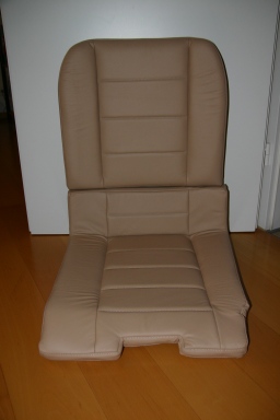
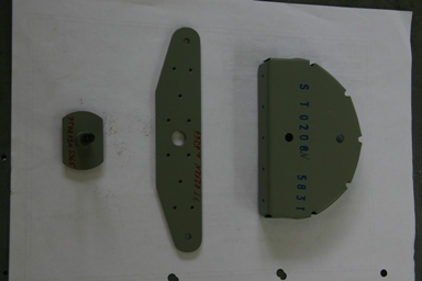
I also unpacked the parcel I received from CZAW last week. Some items were missing when we received the kit (we knew that) and they have sent most of them now. The leather seats were part of the delivery, and they just look perfect.
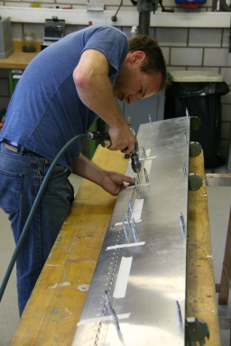
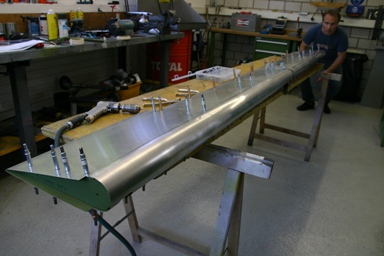
But now back to building. Our kit is a quick build kit, so to convince the EAS that it fulfills the 51% rule we have to build the rudder and the elevator ourselves. As they contain some driven rivets (the rest of the kit uses only pulled rivets) I decided to build the rudder and elevator at my flying club’s maintenance workshop. There we have access to all the required tools as well as the possibility to ask our certified mechanics if we have any questions.
The SportCruiser assembly manual is based on the rudder and elevator being factory built, it therefore does not contain any instructions on how to assemble them. Fortunately the basic design is similar to that of another popular kit, so I used the assembly manual for that kit as a starting point. I also took quite a few pictures, so that I can write an assembly manual that other builders can use in the future.
First Rolf and I started doing some samples to learn how to properly drive rivets. Below my second sample, with most rivets already looking quite ok.
It definitely helps that I made a four year apprenticeship, getting trained as certified mechanic, around 20 years ago before I went studying electrical engineering. Even though I have never worked as a mechanic after the apprenticeship there are some thing you just don’t loose..
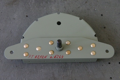
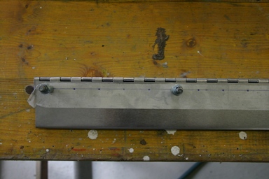
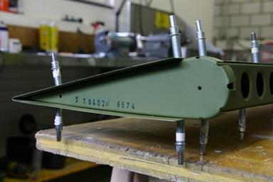
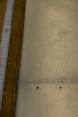
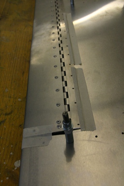
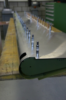
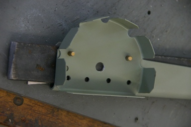
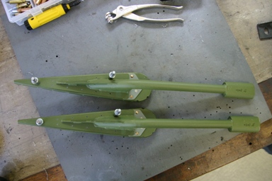
We then started with the lowest rudder rib, which is riveted together with the rudder control lever as well as the lower spine into one unit.
The three parts are held together by four long and 6 medium solid rivets. Here the first hole has been drilled and the parts cleco’d together.
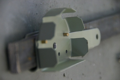
Here the same seen from the back side, with already three clecos installed.
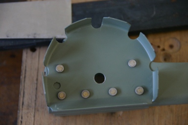
Here again from below, with all holes drilled.
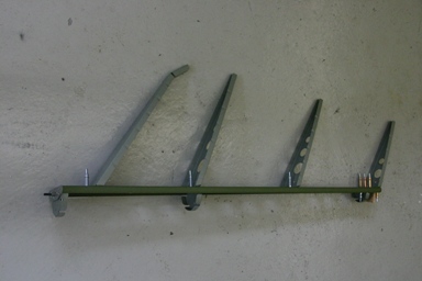
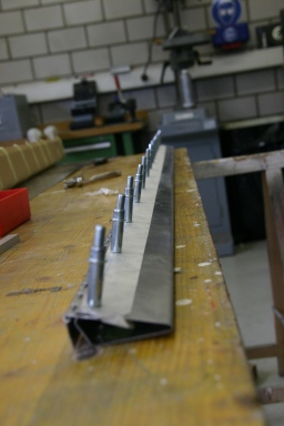
In the end the whole assembly looked as follows:
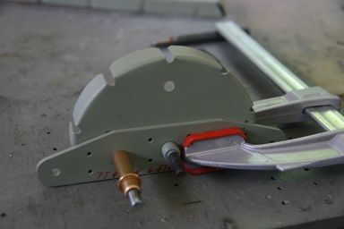
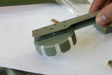
After that we prepared the upper hinges and clecod both the upper and lower hinges to the rudder spar. We then went to verify that the whole assembly properly fits to the fin before riveting everything.
Rolf checking the proper fitment.
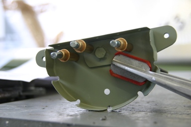
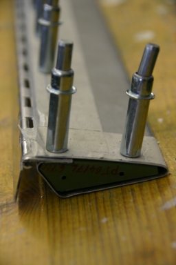
Here the lower end of the rudder spar with the control lever and lower spine attached.
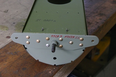
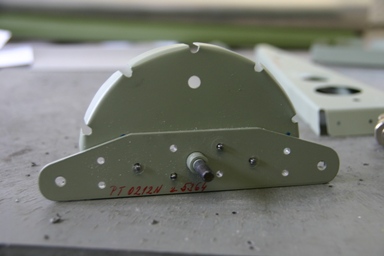
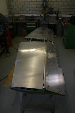
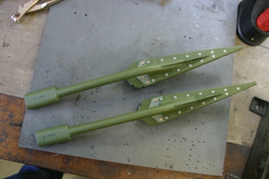
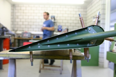
Once all ribs are attached to the spar the whole assembly starts looking like a rudder.
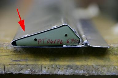
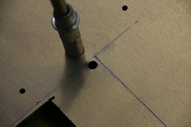
Below the upper most rib as well as the upper hinge (not visible, as it is behind the spar) riveted together. If you think that the left three rivets have a bigger diameter than the right ones you are right. We of course attached the hinge first to the wrong side of he spar (!), so we had to drill them out again and turn the hinge around by 180 degrees. As the holes would not fit perfectly we drilled them to the next bigger size and used bigger rivets. Something like that probably happens to most builders at least once, we concluded that everything should be cleco’d to check first before driving any rivets. Thanks Silvan for the help.
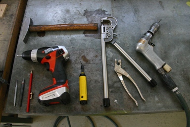
Here the tool we used. In the end we also used a pneumatic rivet gun for those rivets we could not access with the hand
The next step will be to attach the rudder skin.
04.06.2008: Rolf had some urgent business and I did not have too much time too, but I managed non the less to spend some time on the rudder.
When checking which tools I need in the SportCruiser assembly manual I overlooked that specially machined rivet heads are required to form the heads of the AVEX rivets. I sent a mail to CZAW on Monday and they replied on Tuesday that they send some immediately. They will take some time to arrive, however, so I already thought I can’t continue building. Then I remembered that a guy from my PPL theory course is building a Zenith 701 only about 20 km from where I live, and the Zenith kits use the same riveting technology. I called him on Tuesday evening and an little over an hour later I was already home again with his riveting tools. Homebuilders are great people, thanks Sämi.
First I attached the forward ribs to the rudder spar. Here the upper most one as seen from the front…
…and the back.
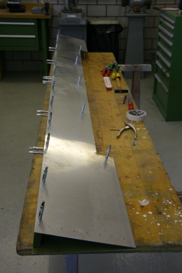
Here the whole assembly of rudder spar and ribs, some already riveted and some clecod. After having riveted one piece the wrong way round on the first day I am getting more careful, clecoing first and riveting only once everything fits perfectly.
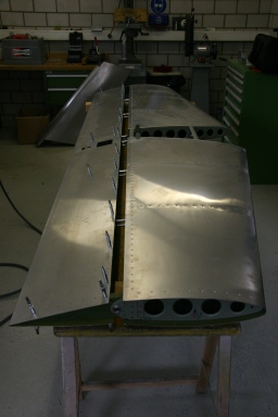
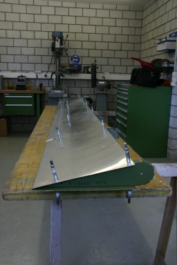
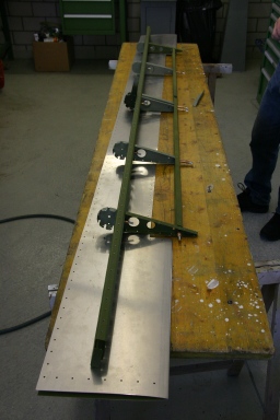
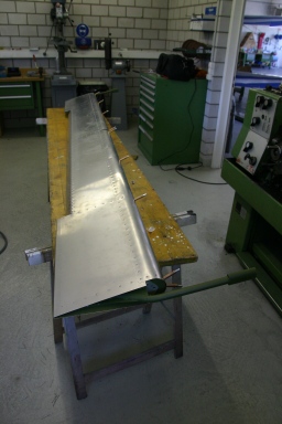
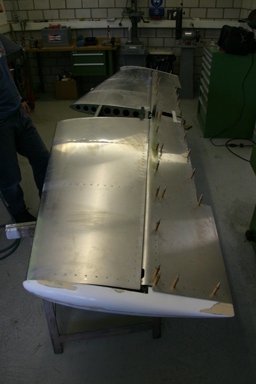
This is what the assembly looks like with the rear skin placed over the spar assembly.
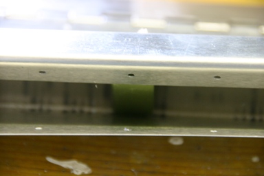
The holes on the skin are pre-drilled, so it was an easy thing to attach the skin with some first clecos. I used a 2.4 mm drill first and then checked that everything aligns perfectly.
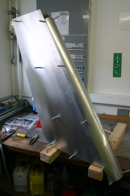
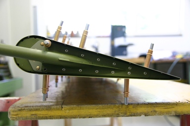
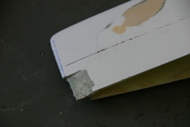
I then took the rudder home to check whether it fits to the fin. And it does so perfectly, with the exception that the skin needs to be trimmed to the height of the fin .
It also moves smoothly thanks to CZAW using ball bearings for all hinge joints on rudders and flaps, but also on control rods etc.
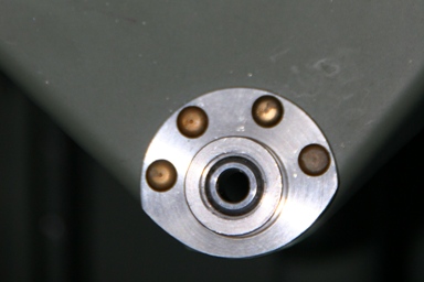
Another detail showing the excellent quality of the kit.
I will have to trim the skin on top of the rudder to align with the fin before installing the pre-molded composite fairings.
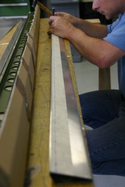
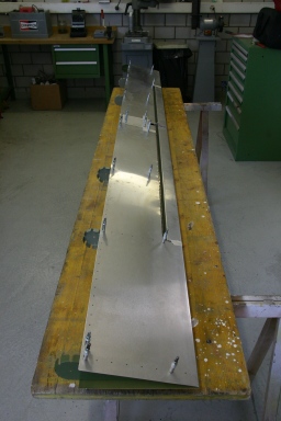
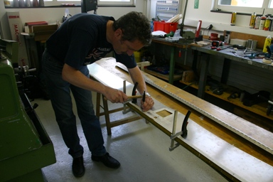
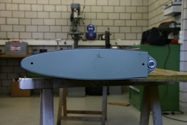
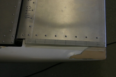
05.06.2008: Today we started trimming the rudder skin to match the height of the fin.
We then continued drilling all holes. We first drilled all of them to 2.4 mm and assembled the rudder using clecos. Once this was done we realised that there was a slight twist in the rudder (around 1.5 cm in one corner). We therefore removed some of the clecos and aligned the rudder on the table so that there was no twist anymore. I then drilled the holes to 3.2 mm as required for the rivets.
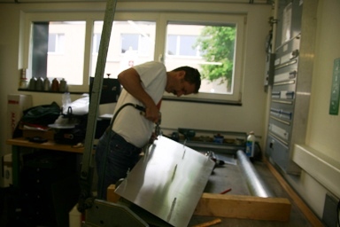
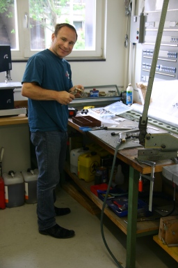
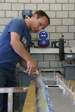
Next we trimmed the front skin to the required size. Here Silvan, the chief mechanic of our flying club’s maintenance shop, shows us how to best use the tin snips.
Yes, it matches perfectly after the trimming.
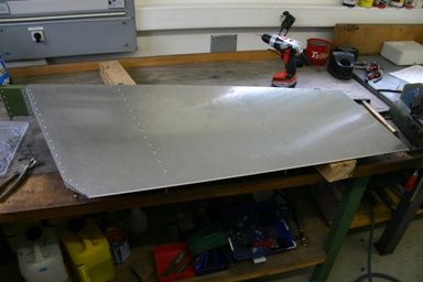
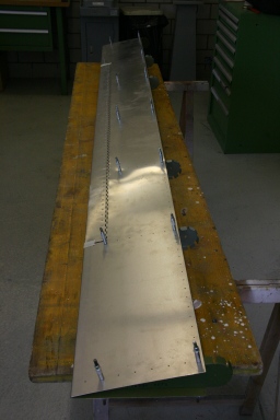
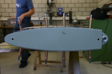
Slowly the rudder looks like a rudder.
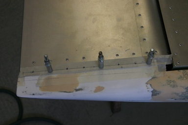
Here one side is fully riveted. The other side is still partially open for the inspection by our building advisor.
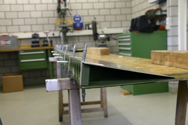
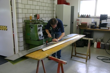
Next we started with the trim flap of the elevator. Quite a job to install all those rivets on what is essentially an aluminium channel.
They are required to hold the piano hinge, by which the trim flap is attached to the elevator.
In the middle and at both ends is a small rib, it was quite a job to put it inside the channel.
06.06.2008: Today we continued with the elevator trim tab. We finished drilling everything…
…then deburred the 60 or so rivet holes and then riveted the whole thing.
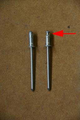
Some rivets do not have sufficient clearance behind the pieces they hold together, like the ones near the trailing edge of the trim tab (see picture below). The rivet can’t be pushed in fully, as it touches the opposite skin of the trim tab.
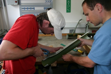
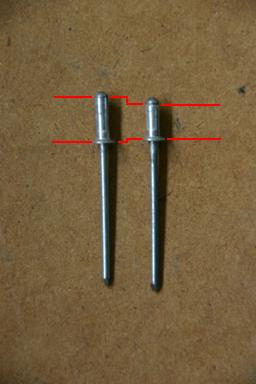
Silvan showed us how to shorten rivets for cases like that. On the left picture a normal rivet (left) and one where the rivet has been cut short with a Dremmel tool. After that the stem is knocked in with a hammer, resulting in a rivet that is as much shorter as what has been cut out in the first step. It takes two or three attempts to make them, especially as the stem should not be cut, but once you got the trick it’s quite easy.
After drilling all holes to the exact size the holes had to be deburred.
Thanks to the pneumatic riveter, which fellow builder Sämi lent us, riveting the trim tab went quickly. We then started assembling the elevator spar and ribs. The elevator is a little more complex than the rudder, so we had to read the plans more carefully.
Always check whether everything is straight if you want to fly straight rather than in circles….
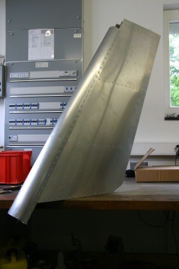
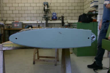
07.06.2008: This morning I received the missing machined rivet heads by mail from CZAW, so I can return the ones I borrowed from Sämi. Then I went to show the rudder to our building advisor, luckily he lives in the same town. He was happy with the result, so in the afternoon I could close it. The result definitely looks like a rudder.
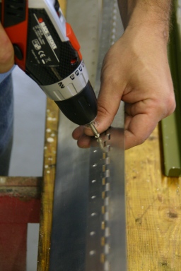
I then continued with the elevator. I finished drilling the skin (approximately 300 holes…) and started installing the end ribs.
I checked whether the elevator fits the stabiliser, and again it just falls into place.
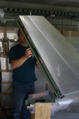
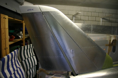
Once back at home I temporarily installed the rudder to the fuselage (I can’t install it permanently, as my workshop is a little too short…). It fits perfectly, everything looks straight, and even the fin and rudder fairing match perfectly. I will wait with riveting them in place until I have made up my mind whether to install an VOR antenna as well as a strobe in the fin (CZAW even run a conduit there to simplify cable installation)..
08.06.2008: I only found a bit of time today to start looking at the next steps, the rest of the day belonged to the family. Next week will be difficult too, I will see what I will manage to do.
18.06.2008: I had to go to Genoa in Italy on a business trip, so not much happened. While I was away, however, the last missing items arrived from CZAW. This especially includes the cowling, but also the gas struts for the canopy.
I also decided after some mail exchange with Chip Erwin from CZAW to cancel the TruTrak autopilot. We intend to switch to the one which was announced from Dynon, as it integrates much better into the Dynon avionics. The servos are mechanically compatible, so no changes are required on that side.
21.06.2008: I finally managed to spend again a full day working on the elevator. The starting point was that the inner frame (spar and ribs) have been assembled and the skin drilled, as well as the trim tab assembled.
As the next step I marked the part of the skin to be cut for the trim tab.
I drilled holes in all corners and also cut away the metal roughly using a rotary tool. Silvan showed me this trick, as afterwards I would only have to cut small strips, which goes much easier.
Then I disassembled the elevator and started cutting.
I managed to cut very straight lines, which surprised myself. A masking tape glued parallel to the line to be cut helps as guiding line.
Here a picture of the final result, with both sides cut and the tapes removed…
…and here with everything re-assembled.
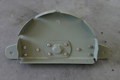
After that I drilled the holes for the trim servo cover and then temporarily attached the trim tab. When doing that I found a small problem. The bracket on the trim tab, to which the servo attaches by means of a short rod, did not line up with the cut-out in the elevator skin through which the rod goes. I then measured everything against the plans. The bracket on the trim tab is in the right place, 100 mm from the centre of the elevator. I therefore downloaded the drawings of the Ray Allen T2-7A servo that is used. When calculating from those drawings where the rod will be if the servo is installed according to the plans I found out that the cut-out is indeed at the wrong place. I therefore decided to let the bracket on the trim tab where it is and to enlarge the cut-out. I can still install a small cover once everything is installed.
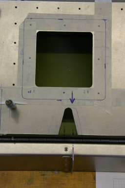
A cut-out is required in the spar at the end of the elevator, to which the trim tab is attached, for the servo rod. I made it as wide and deep as marked on the plans, just at the correct location.
Then I drilled the front ribs.
Once everything was re-assembled all looked ok.
Here the elevator with the trim tab temporarily installed, as seen from top (left) and bottom (right). It will probably take me another day to finish it.
27.06.2008: Rolf and I managed again to take Friday off for working on the SportCruiser, great.
First we pre-drilled the holes into the piano hinge of the trim tab, then attached the trim tab to the elevator with the hinge on top of the skin (in will be below the skin for riveting), and used it as a guide to drill the holes into the skin and the underlying rear spar. It all turned out perfectly straight.
On the other side we had to drill the holes without any such guide, so we took the skin off, marked all the positions of the rivet holes with a pen, punched guiding holes with a centre punch and drilled the skin alone without any underlying structure (we just drilled into the plank we use as a table).
After that we re-assembled everything and drilled the holes into the rear spar.
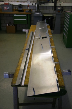
We then started with the front skin of the elevator. It comes pre-bent and with holes already pre-drilled on one side. That allowed us to fix in on one side, then slide it under the main skin on the other side (even though it will be on top when riveted) and use the holes in the skin as guide. The front skins are a little too wide for perfect fitting, so they had to be trimmed in the end. The result of two meters of cutting with the hand snips resulted in a blister on my hand…
Again everything had to be assembled, de-assembled, assembled again etc., I slowly can’t see clecos anymore.
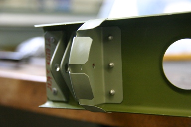
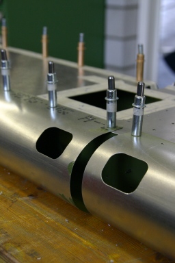
Here a detailed view of the area around the centre of the elevator. The two holes in the front skin will be on the lower side and are needed to install the bolts into the rudder hinges. The bigger hole in the back is needed to install the trim servo.
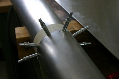
We then started with the most complicated sub-assembly so far. It consists of the elevator horn, to which the elevator control rod is attached, and the two front ribs that fix the elevator horn to the elevator main spar. Solid rivets with flush heads are used, with the flush heads inside the elevator horn.
We pushed the rivets through the holes from inside the horn, then slid an iron bar into the horn and riveted with the pneumatic riveter from the outside. Silvan, the chief mechanic of our flying club, showed us how to do this, as the assembly manual of the SportCruiser again does not cover the elevator.
Here the first two rivets before riveting,…
…here another view…
…and here the first two rivets seen from inside the horn.
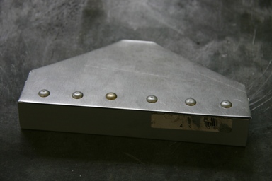
From the outside the final “product” looks like that.
We then re-assembled the whole elevator, checked whether everything was straight…
…and test fitted the elevator to the stabiliser. Everything matched perfectly, what a positive result at the end of the day. I have to admit that pre-punched skins and spars really help to assemble perfectly even without any jigs.
After that we drilled all holes to final size, disassembled everything and started de-burring all holes. The elevator alone uses around 500 rivets, with each holding at least tow parts together. That gives more than 1’000 holes, and each has to be de-burred on both sides.
28.06.2008: Again a full day of building for Rolf and me, things are speeding up.
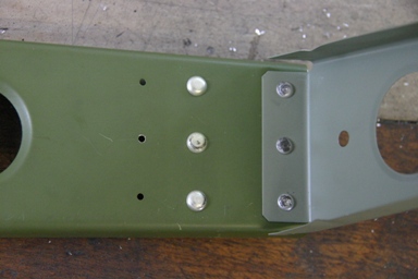
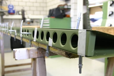
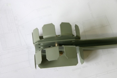
We started with preparing the installation of the mass balances on the elevator. To do that some reinforcement had to be riveted to the end ribs of the elevator. These reinforcements also serve as support for the bolts holding the elevator to the stabiliser.
Some of the rivets used are solid rivets with flush heads.
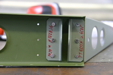
With the flush rivets set the whole assembly looks as follows:
From the other side it looks as below. We slowly get the feel for solid rivets, especially when the can be installed with the hand squeezer.
The two outer rivets are solid rivets too, but with normal round heads. From a manufacturing point of view it would make more sense to use sunk heads on all rivets, but you can not understand everything….
Here the whole thin close up.
Here the mass balances are clecod to the ribs…
… and here they are riveted using avex rivets. The mass balances come pre-welded, with pre punched holes, so the whole process of installing them is straight forward.
After that we started assembling the elevator for the last and final time. All holes are drilled to full size and de-burred.
Here the inner structure (spar and ribs) is already riveted, and the skins are attached with clecos. It is amazing, how a weak and wobbly structure gets very sturdy and rigid as soon as everything is riveted.
Below the elevator with the upper side fully riveted (approximately 250 rivets), the other side remains clecod until our building advisor has seen it. Many thanks again to Sämi, who lent us his pneumatic riveter, I think I would not have survived pulling 250 rivets with the hand riveter….
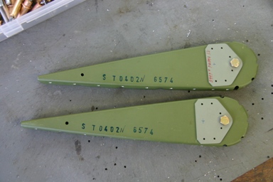
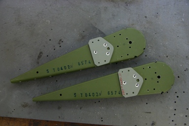
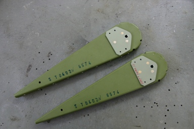
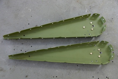
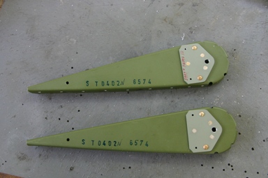
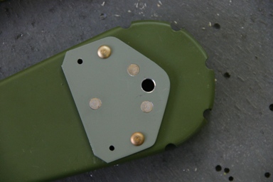
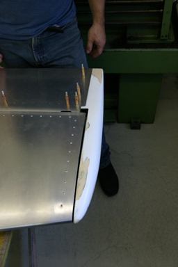
With some time left we started attaching the composite elevator tips, which cover the mass balances. They fitted quite well, only a few millimetres had to be trimmed at the rear end.
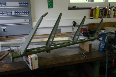
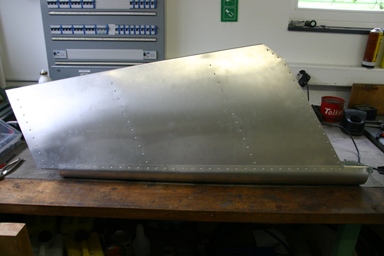
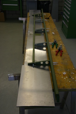
The whole stabilizer and elevator assembly will look like that:
Two closing ribs still had to be installed too, they close the end of the stabilizer toward the mass balances.
The same process: pre drill with 2.4 mm bit, install with silvery clecos, drill to full size with 3.4 mm bit and use copper clecos, disassemble, de-burr, re-assemble with copper clecos…
…and then rivet.
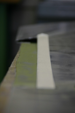
Here the composite elevator tip as trimmed.
The holes to rivet the composite fairing line up with the ones that hold the last rib of the elevator, which makes it easy to mark them.
I hope I receive the trim servo next week, me need it to finish the elevator.
In the evening I continued reading a book I bought in Australia. It is called “Flight”, from Tom D. Crouch. It describes the history of aviation in detail, with emphasises on the early years. Highly recommended.

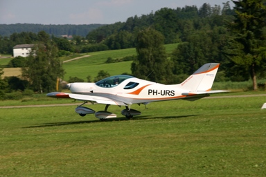
30.06.2008: Yesterday I received a mail from Urs, a SportCruiser owner living near Zurich. Last week he flew his Dutch registered SportCruiser PH-URS from the Netherlands to Switzerland, which is probably around 700 km, just to realise after landing that the tank was still half full…. His SportCruiser will be stationed in Mollis (LSMF), and he is looking for a mechanic to do the maintenance on his plane. As I am the technical manager of the EASA-145 certificated workshop of our flying club in Lommis (LSZT), and as we already have a number of Rotax powered planes at our airfield, I of course proposed that he should come to see whether we could do the maintenance for him. He immediately mailed me back and we agreed that he would drop in for a visit in the afternoon. I therefore cut my working hours short and was at the airfield at 15:00. Shortly afterward I heard the familiar Rotax sound and there he was:
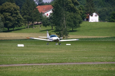
The first landing of a SportCruiser in Lommis! Let’s hope that many more will follow. Of course it immediately attracted the few people present on a Monday afternoon, one of them “Kitfox”-Thomas, another homebuilder, who like Urs flies for a living for Swiss International Air Lines.
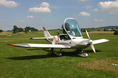
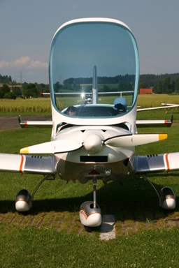
Our two mechanics Silvan and Martin immediately “jumped” at the plane, and within minutes the cowling was off. They really liked what they saw, which I considered a good sign for the quality of the plane. Below a few pictures of the SportCruiser:
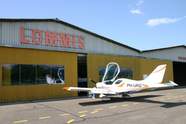
I of course hat to take a picture of the SportCruiser in front of the workshop….
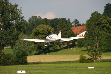
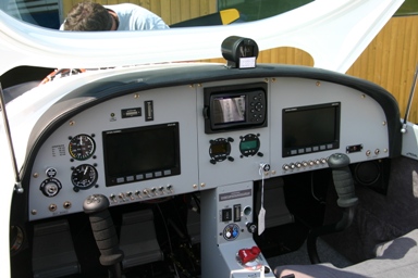
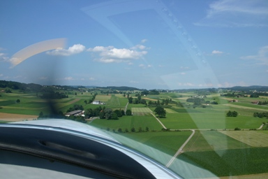
After discussing maintenance issues we of course went for a little tour. It was the first time I flew in a SportCruiser since we visited CZAW in December 2006, and it felt just great. It really flies nicely, with a superb view thanks to the huge canopy. I was also amazed how well the Dynon’s can be read even in full sunlight and with the sunglasses on. Below Urs shortly after take off:
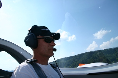
Urs let me fly the whole flight and I only handed controls to him on final, I therefore only managed to take the one picture below:
Here a shot from the front after landing…
…and here Urs (right) and myself.
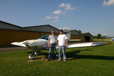
Shortly afterwards Urs had to leave again, but he will be back soon for his 25 hours check.