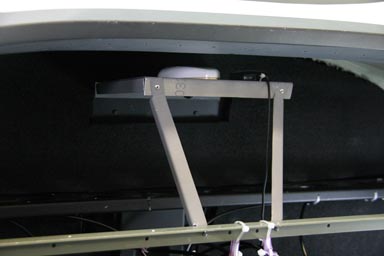
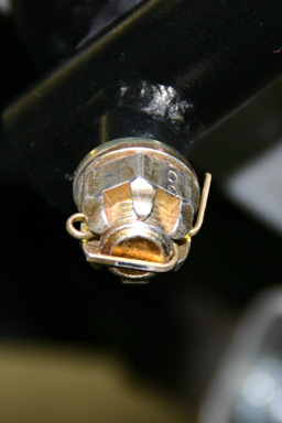
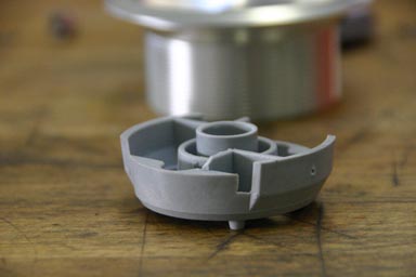
03.09.2009: I finished the GPS mount today! First I made two small angles against which the foldout door that carries the GPS rests when locked.
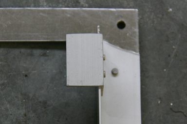
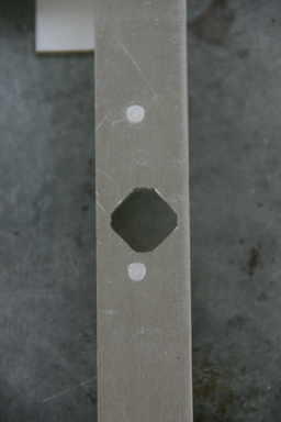
I then made the holes for the two locks. To prevent the locks from turning in the holes they are not round but nearly square, so the holes need to be square too. I made them by drilling a round hole and then making it square with a file.
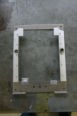
Finally I riveted the fold out door to the hinges, installed the locks and here it is…
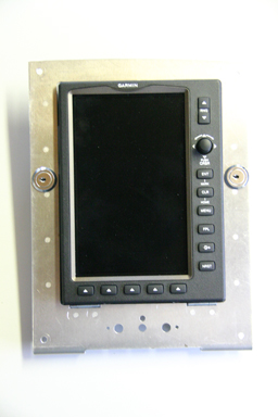
It works perfectly. To install the GPS I just have to push it into the hole where it latches in by itself. To take it out I have to unlock the door, fold it out and release the latch by pushing on a small lever on the back of the GPS. It looks at least as neat a the AirGizmo mount, takes less space in the panel (there is about 2 mm left on top and at the bottom), the GPS is protected against theft and the hole thing saves me around 150 $.
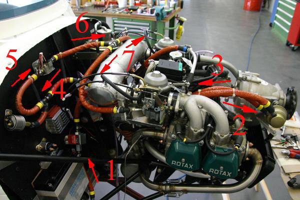
Next we installed the oil cooler. We had to remove the muffler to get to the screws, but finally it fitted perfectly. We also added the oil hoses from the cooler to the thermostat.
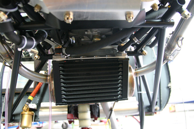
Here the thermostat, just mounted with cable ties and spacers to the engine mount. We will still add a mounting bracket as on the factory planes.
04.09.2009: I did the last finishing touches to the panel:
I then removed the locks and brought it for painting. I will be in Lille, France, from Monday to Wednesday next week, and can pick it up on Thursday.
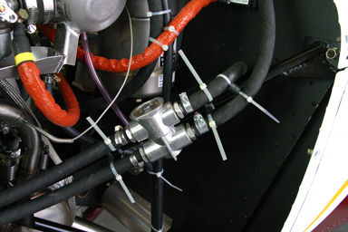
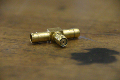
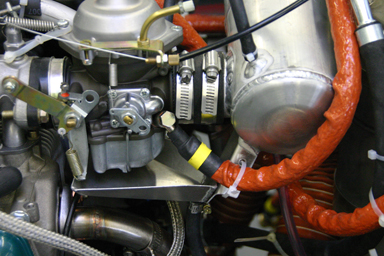
05.09.2009: Today I continued with the fuel lines. As on newer factory built planes we also placed the fuel flow sensor after the vapour lock return line and just before the fuel lines splits to feed the two carburettors. A restrictor has to be added to the vapour lock return line to prevent that an excessive amount fuel flows back into the tank, which would also lower the fuel pressure. A Y-shaped fitting made of aluminum was supplied with the kit, but I don’t like it (it looks too fragile) so we made one ourselves from a T-shaped fitting. We made a small brass plug with a tiny hole in it that we then pressed into the T fitting. Somewhere in the Rotax manual I read that the the hole should have a diameter of 0.35 mm. Ours is a bit bigger, as we did not have such a small drill, so we will have to see what the effect will be.
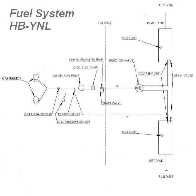
The schematic of our fuel system is now as shown below:
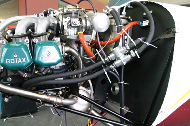
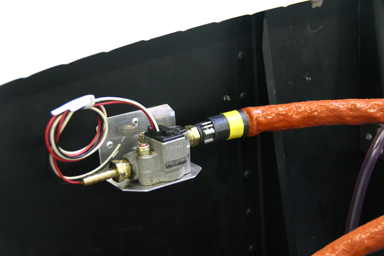
We made a mounting bracket for the fuel flow sensor to put it on the firewall, with the resulted that we now have a neat and clean layout of the fuel lines.
I also turned the nipples to which the fuel hoses are connected backwards and drilled small holes in the air box brackets to attach the fuel hose with tie wraps. Unfortunately I tightened the screws that hold the nipples too much, so one got damaged, which means I will have to order two new ones. That’s one of the first items I damage during the assembly.
Next I installed the remaining safety pins that secure the front gear leg and the engine mount:
Then I installed the air hoses between the air box and the air filter, respectively the exhaust heat exchanger.
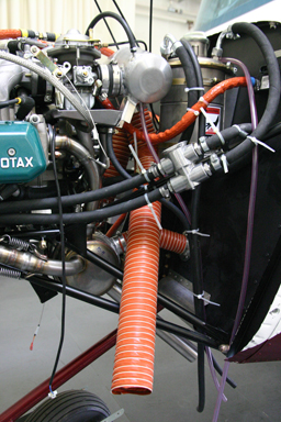
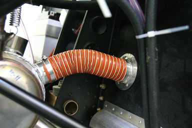
The last item I installed today was the air hose between the heat exchanger and the heater flange. That is to feed hot air into the cabin when flying in winter.
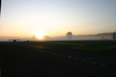
06.09.2009: Today was one of those mornings where I love to be at the airport. There was the first thin layer of morning fog which usually indicates that summer is coming to an end, followed by a beautiful sunrise.
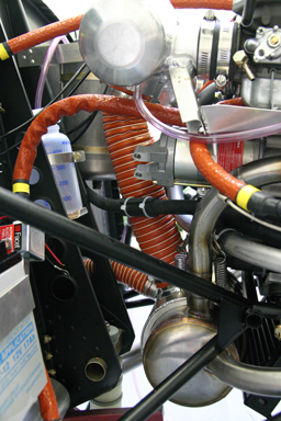
Today I finished the fuel lines. As I placed the fuel flow sensor ahead of the firewall I had to make one section of isolated fuel line myself from a plain fuel line and a fire sleeve. I asked Silvan how to pull the sleeve over the fuel line and he told me to use a wire which runs through the sleeve and the fuel line:
Here the resulting layout of the fuel line:
- from the gascolator to the electric fuel pump
- to the mechanical fuel pump
- to the T where the vapour return line goes off
- to the T where the line to the fuel pressure sensor goes off
- to the fuel flow sensor
- to the T where the line splits to the two carburettors
- to he two carburettors
The layout has several advantages over the one used / recommended by the factory. First of all the length of the fuel line is kept short, second only a minimum of fuel line is over the engine and third the number of fittings is as low as possible.
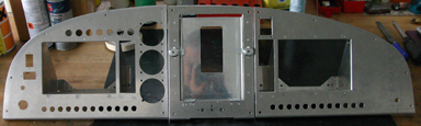
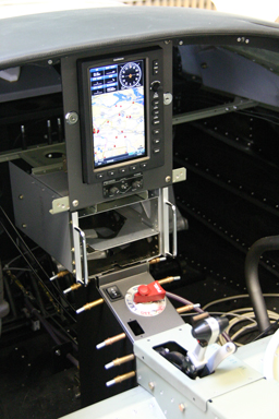
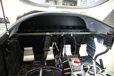
10.09.2009: I went to pick up the panel tonight. Even though I am quite busy with other things I could not refrain from installing a few instruments just to see what it looks. I have to say I really like the dark colour, it’s not black but anthracite.
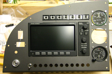
Above the Dynons I will install the following warning lights:
- Engine Management System alarm (red)
- starter engaged (red)
- canopy unlocked (red)
- alternator failure (yellow)
- fuel pump (green)
- pitot heat (green)
- flap down (green)
To the right of the Dynons I have the backup ASI (top) and altimeter (bottom), in between there will be a FLARM. For those who don’t know FLARM, this is a traffic and collision warning system with which most gliders are quipped and with is also more and more used by helicopters and other general aviation aircraft in central Europe. Especially gliders are difficult to see, mostly when you meet them head on, and FLARM warns you if there is a plane on a collision course. I get a 5% rebate on the annual insurance if I put one in my plane, which means it pays for itself in just two to three years. To the left of the Dynon screen there will be the trim indicator and the parking brake knob, below all the switches.
When updating my log I noticed that today we passed the 1’000 hours mark of building time. This is however only the time Rolf and I spent with actual building work. All time spent doing paperwork, reading manuals, ordering parts, writing documents etc. is not included (I did not count these hours…).
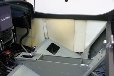
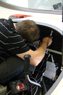
12.09.2009: I could only go to the airport for about two hours today, luckily I live only 15 minutes away so it is still worth it going there for such a short time. I took the centre console pieces with me and started assembling it. First however I had to install the fuel selector switch and the flap switch and indicator.
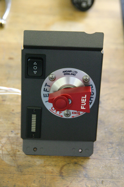
The three screws supplied with the fuel switch were of the standard yellowish type, which would not have looked nice on the aluminum front plate, so I used some stainless steel ones. Unfortunately the screw heads were too big, which means they would have extended over the edge of the front plate, which again would not have looked nice, so I put them on the lathe and made the heads smaller. Now both proportions and colour look nice.
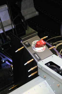
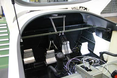
Below the centre console installed. I like the anthracite, it gives the panel a “professional” look…
13.09.2009: I found a wonderful short video on the homepage of the Swiss television about a photographer who makes a living from taking aerial pictures of the alps. The pictures probably explain best why I am building a plane…
17.09.2009: Today I installed the vapour return line. First I had to enlarge the hole in the firewall, through which line line goes. Into that went a grommet, and finally the fuel line. I forgot to take a picture with the line installed…
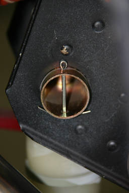
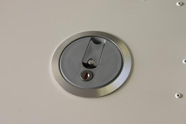
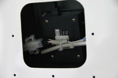
Then I finished the GPS installation. Below the centre section of the panel with the GPS installed. To remove it, the two small locks on both sides have to be opened. The GPS then folds out, giving access to the small lever on the back side which releases it.
19.09.2009: Last week was again one of those weeks where I was extremely busy at work, so not much progress on the SportCruiser. I however spent quite a few hours updating the CAME (Continuing Airworthiness Management Exposition), which is the document describing the organisation and processes of the newly established CAMO (Continuing Airworthiness Management Organisation) of our flying club. Starting next month all planes in Europe operated commercially have to be managed by such an organisation, which does manage the planes paperwork (maintenance planning, AD’s, SB’s etc.). Even though we are a private club we do make some sightseeing flights for the general public, which is considered a commercial activity. The same is the case when we provide flight training to trainees which are not member of our club, which happens sometimes. Both are considered commercial operations even though we do not really make money with it.
I also updated the MOE (Maintenance Operation Exposition), which is the document describing the organisation and processes of the Part-145 certificated maintenance organisation of our flying club, of which I am the accountable manager. We had to update it to provide maintenance to operators of so called Annex II airplanes, which are those not regulated by EASA (gliders, balloons, historic aircraft, experimentals etc.). Starting next month so called owner/operator maintenance is interpreted more restrictively, which means a number of the privately operated airplanes at our airport will have to seek maintenance from our maintenance organisation, and many of these planes are Annex II.
20.09.2009: This afternoon I continued with the fuel lines. They are running from the wing along the main spar box to the fuel selector in the centre console. All fuel lines are made from standard automotive fuel hose, and where they pass into the center console they have to be protected by a small section of rubber grommet. The assembly manual recommends to use super glue to fix it, and indeed that works well. Below the small section of grommet can be seen glued to the removable metal cover on one side of the centre console.
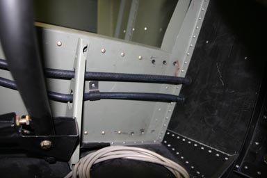
The fuel lines are held in place by P clips. The lower line is the fuel line, the upper one the vapour return line.
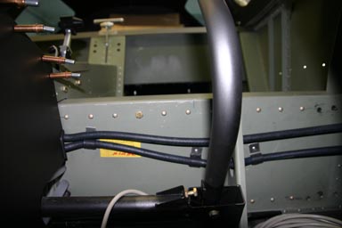
Below a shot where the two lines pass through the fuselage side wall towards the wing. I installed grommets where the lines pass through the wall, even though the assembly manual does not mention any. The vapour return line will be attached to the fuel line by using tie wraps.
Foam padding is used on the side walls. It comes already pre-cut with the kit, so it’s just kind of a puzzle to find out which bit goes where. I will use contact adhesive to attach them to the wall. The upholsterer who repairs upholstery on our club planes recommended that I add a thing layer of cardboard between the foam and the leather that goes on top, so that it makes less wrinkles.
21.09.2009: Another day at the workshop. We started by taking one of the wings off the wing stand. Rolf fitted the mounting plates for the landing lights and I made the window that goes in front of it. We then discussed whether we shall glue the window in (we expect the LED’s to last longer than the plane) or to mount it with screws, and finally agreed on the later version for simplicity. I will first try to find some clinch nuts before considering anchor nuts, as they seem to be a bit of an overkill.
Next I installed the fuel caps. Silvan gave me a sealer to install the mounting rings, into which the caps go. There is a TB for the fuel caps that asks to modify them in case the cap swells a bit due to certain fuel additives. As the TB is easy to implement I did it preventively before any swelling is detected.
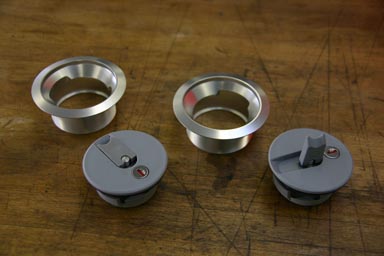
Below the lower part of the fuel cap. The innermost “ring” has to be shortened by a few millimetres.
Here the tank before installing the filler cap…
…and here with the cap installed.
Next we continued with the NAV/Strobe assembly. I made some small brackets to prevent the cables from sliding back into the wing tips, as I don’t want to have to cut the wing open to search for the cable ends.
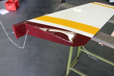
We also installed the stabilizer for the first time.
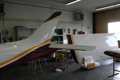
This allowed us to permanently rivet the stabilizer fairings. I will hand paint the rivet heads so that they blend in with the fairing.
Rolf installed and wired the trim servos in the elevator and the aileron, wile I installed some of the cables in the fuselage.
25.09.2009: I spent a few hours today doing preparatory work for the wiring of the plane, of which I could not really take pictures. One of the things I did was to clarify which cable will go into which of the six plastic tubes that run underneath the seats and the centre console.
The aim is to keep interference between the different cables as low as possible (e.g. separate the low voltage audio lines for the headsets from the high power antenna cables or the cable to the flap motor). I have flown in enough planes where such interference was audible in the headset.
28.09.2009: This is the last entry for this month, as I will be off again on business for three days, this time to London. There are probably more SportCruisers in the US, but the UK definitely has the highest number of homebuilt SportCruisers. I will pay attention, maybe I will see one in Heathrow…
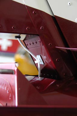
Today I installed the wires for the rear light / strobe. I have not yet build it, but it will definitely go into the trailing edge of the rudder. I thought for quite a while how I could run the wire there, especially as the rudder is already finished. I then noticed a small hole at the bottom of the rudder just behind the spar. I figured out that I could run the wires into the rudder there, then inside the rudder back along the lowest rib and then up along the trailing edge to where the light will be. Like that the cable is well protected and held in place as it goes up behind the ribs. To install it I pushed the cable in through the hole (into which I inserted a grommet), an then fished it out from the rear end with a hook made from a wire. Once I have decided how high up the light will go I will drill a hole there and then push the wire up inside the trailing edge.
Here the wire going into the rudder and temporarily out near the trailing edge where there is a hole anyway.
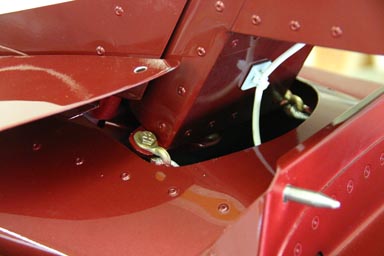
Below a view of the rudder installed with the wire going through the grommet. I also added a tie mount to secure the cable at the base of the rudder. Like that the cable only moves very little even at full rudder deflection.
Finally Rolf and I attached the rudder cables to the rudder. Cool, we can now move the rudder with the pedals…
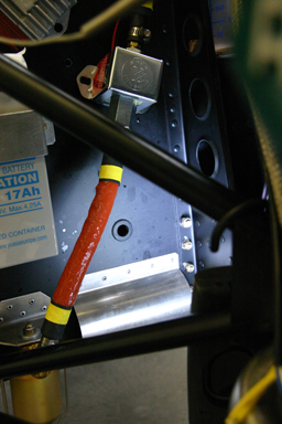
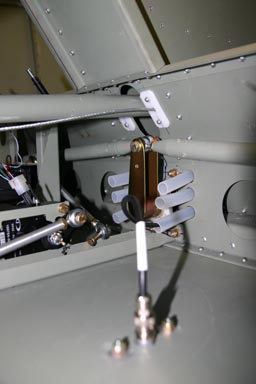
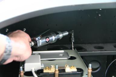
Next I mounted the small mounting plate which goes behind the panel. The shunt resistor, trim relays box and altitude encoder are mounted onto that plate.
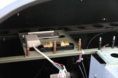
Luckily Silvan has a 90 degrees angle drill, as the holes have to be drilled underneath the front fuselage.
Rolf and I then added the soundproofing foam sheet onto the firewall (cockpit side of course). This is quite a job, as you nearly have to creep head on into the fuselage…
Rolf volunteered to put the glue onto the lower part of the firewall, as he is less tall than I am.
We added the mat with contact adhesive. Tricky, as once the mat touches the firewall you can’t move it anymore, but it worked out quite well. I am looking forward to seeing how much difference the soundproofing will make. I will be able to compare our SportCruiser with the one ordered by the club, which does not have soundproofing.
Having added the soundproofing allowed me to permanently install the GPS antenna pedestal. The three (!) GPS antennas (GNS430, GPSMAP695 and Flarm) are mounted on it next to each other underneath the front fuselage.