01.08.2009: It is the Swiss national holiday today, which is a day off, so I could spend two hours at the airport. I first had to get back into the project again after three weeks of absence, then I continued “plumbing” the engine.
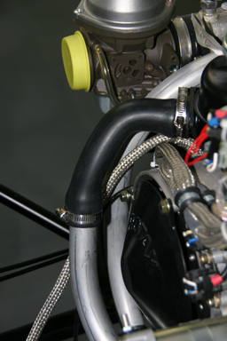
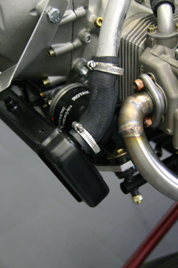
I first tied the water hoses to the engine mount as described in the assembly manual so that they won’t rub against anything. This includes adding a protective sleeve over the hose, which is nothing more than a section of coolant tube sliced open.
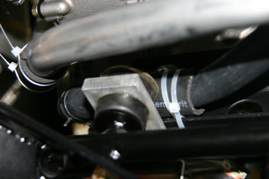
Then I ran the lower water line from the water cooler outlet to the water expansion tank on top of the engine. The required hose clamps were missing from my kit (about the only thing), but I had ordered some before the holidays. It wasn’t that easy to find narrow ones made of stainless steel, as most shops only carry wider ones which are galvanized, but once more Silvan knew a supplier.
Above the attachment of the water line to the water cooler, below the upper attachment to the coolant expansion tank.
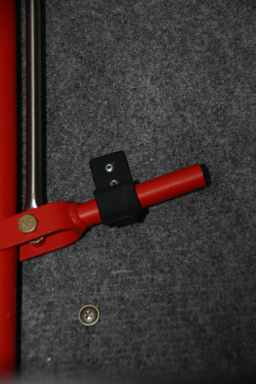
I also ran the brake lines along the gear legs. I fixed them temporarily using masking tape, as I first have to figure out how they should be properly fixed.
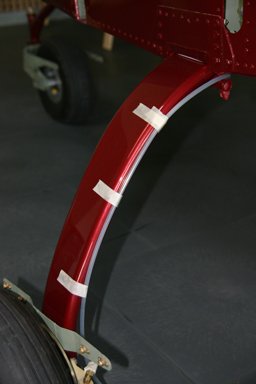
02.08.2009: From what I could see on pictures I took last summer from the SportCruiser of Urs, two brackets are used to fix the brake line to the gear legs. I also saw that it is protected with pink tube from where it comes out of the fuselage until roughly where it runs behind the gear leg (see below).
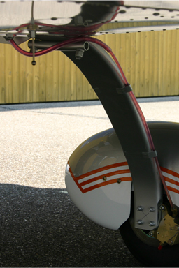
I posted a question on the Yahoo SportCruiser Forum how to fix the brake lines and Kevin answered that he got the above described brackets with his kit, but they would not hold the lines properly. He therefore switched to standard tie wraps. I guess I will do the same until I get to the factory one day to pick up some brackets.
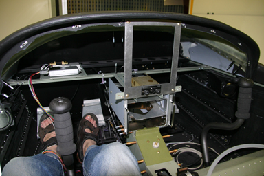
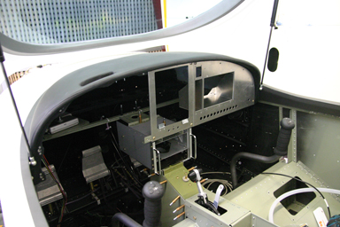
09.08.2009: I continued today with the centre console, which I have to finish soon. Painting the panel, wiring it, installing the fuel lines and finishing the interior all depend on finishing the centre console. There are however two major issues I have to solve first. I have to design a mechanism which allows me to fix and remove the Garmin GPSMAP 695, as I want to be able to take it home for flight preparation, and secondly I have to build a support for the two Garmin units able to withstand 6 g, which means around 28 kg of load.
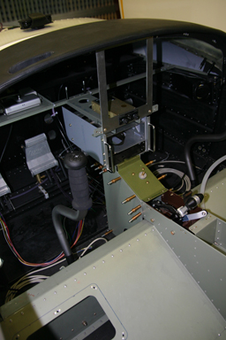
I also started installing the plate which holds a number of electrical items, such as the current measuring shunt, the altitude encoder and the relays required to have trim controls on both sticks.
15.08.2009: After being abroad for a week I continued with the canopy. Last week I managed to borrow a trailer again to transport the canopy from the painter to the airfield, but I just had the time to throw it onto the fuselage.

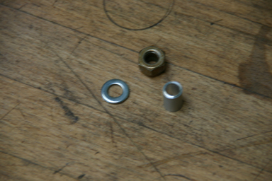
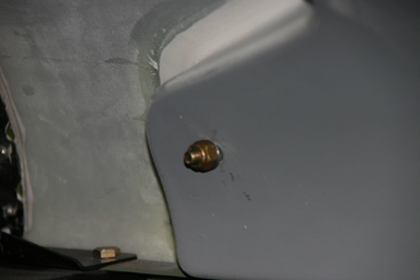
The canopy is installed with two screws. What really surprised me is that even these two screws go through two small ball bearings, which is a sign for the quality of the kit. Due to the shape of the inner surface two short bushings are required so that the nuts don’t press onto the composite surface, but unfortunately they were missing from the kit. As I have already done before I just made two from stock aluminum.
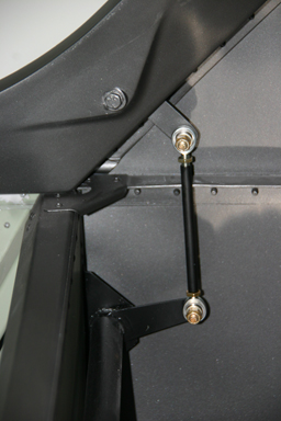
After having installed the two screws I installed the gas struts which keep the canopy open. Easy, just two screws per strut which go into threaded plates inserted into the canopy frame during layup.
The canopy is locked with two “hooks”. I read about some builders having problems to open the canopy again after locking it for the first time, so I did the first trials sitting inside as advised. Like that I could have adjusted the linkage if the canopy would hot have opened again, but everything worked fine.
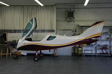
Below the result, in both open and closed position. Cool, now I can already sit inside an close the canopy and make engine noise…
I then continued with the GPS mounting, more on that later.
17.08.2009: Today I played a bit with Photoshop…
I also spend some time doing proper work, such as ordering the battery as well as the annunciator lights. And finally I continued with the GPS mounting.
18.08.2009: I bought the battery today. I asked a number of builders what to use and ended up buying a YUASA 17-12 sealed led battery. The company importing them to Switzerland is only a few km from where I work, so I bought one directly from them, which cut the price nearly in half compared to buying if from a distributor, or a bike shop. The battery has the same shape and size as the one used by the factory, so it fit perfectly.
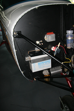
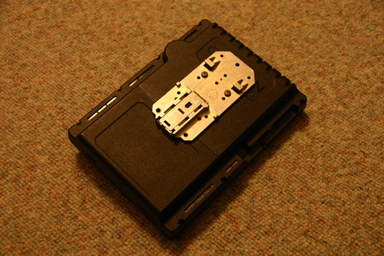
I then continued with the GPS mounting. Here some pictures taken late at night at home, therefore the poor quality. First I mounted a hat rail mounting plate to the rear of the GPS, where the joke mount is normally attached. I allows me to clip the GPS to a section of standard hat rail.
I then installed a kind of door to the center panel section, which folds out to give access to the rear of the GPS.
Here another picture which shows the hat rail installed to the rear of the “door”.
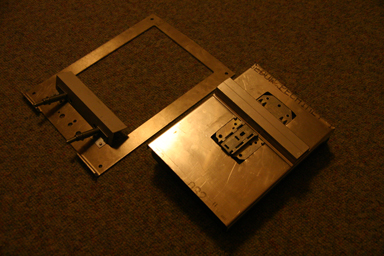
Like that I can clip the GPS into the door without having to use screws, as kind of a quick mount, and it holds very well. I hope to finish it by the end of the week to get the panel painted next week.
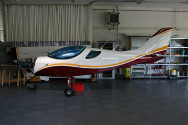
22.08.2009: The plan for today was to go to the annual fly in of the EAS (Experimental Aviation of Switzerland) in Buochs (LSZC). Buochs is basically a military airport, but also home to the Pilatus aircraft factory. As my plane is not yet finished I took the Piper L4, HB-OXI, of our flying club to go there.
When I arrived at the airport in the morning I saw two aerobatics planes parked in the workshop in front of my plane:
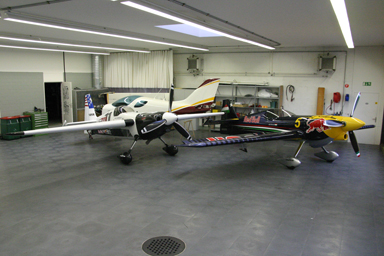
Having a closer look at them I noticed to my surprise that they are two of the Red Bull Air Race aircraft, flown by

and

Cool, I hope they infect my plane with some kind of performance virus…
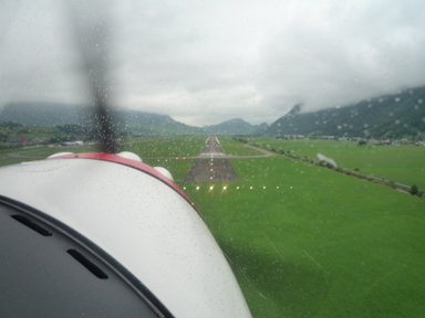
As predicted by the weather forecast the flying conditions between Lommis and Buochs were marginal at best. The L4 is perfect for such conditions, as it is much easier to find a way between the hills and clouds at 650 knots than at higher speeds, and as one can also literally turn on a dime. We non the less arrived safely in Buochs, but only after crossing some passes at exactly minimum flying altitude. When I was turning onto final the guy on the tower even lit the approach lights, which would not have been necessary as the runway is 1940 m long, more than enough for an L4.
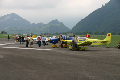
Above part of the flight line, below the “delegation” from Lommis (yellow and green L4, white Kitfox and yellow Breezer).
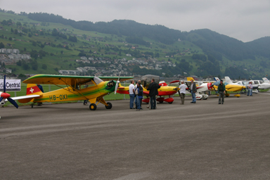
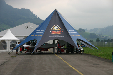
A general aviation fare was organised for the same weekend in Buochs. The number of exhibitors was about as marginal as the weather, but Czech Sport Aircraft had a nice booth with a factory SportCruiser on display.
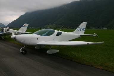
Early in the afternoon a SportCruiser from the UK arrived. I chatted a bit with the owner, he told me that this was his first trip abroad in it.
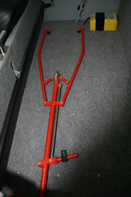
I had a look at some of the details on the factory aircraft which I still have to do, such as how the carpeting and the leather interior are installed. When looking at the towbar I realised that three pieces in my kit which I have been wondering since months what they are used for are brackets to fix the towbar in the baggage compartment.
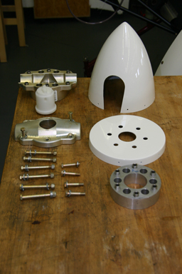
The flight back to Lommis was less difficult, as the weather had improved quite a bit during the day. I still had some time after landing so I started mounting the propeller hub to the propeller flange. On the left below all the bits and pieces, on the right the propeller spacer, spinner plate and rear half of the propeller hub installed.
23.08.2009: Kitfox Thomas sent me a few photos from the flight we did yesterday to Buochs. Actually Rita, his wife, took all the in-flight pictures, as Thomas was busy finding holes in the clouds. The first picture shows quite well why we hardly reached the circuit altitude of Buochs during the entire flight…
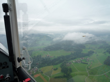
The small plane in front of the cloud in the picture above is the L4 flown by me. Below the Kitfox on short final. One can see the runway lights activated for us, which looked quite cool. In Buochs small planes make a left hand circuit on runway 25, but jets a right hand circuit around the mountain on the right as the valley is too narrow for them. Must be special if you don’t see the airport during the circuit…
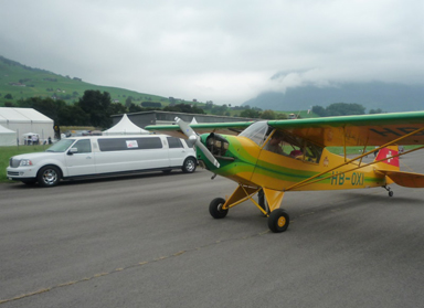
Below the Limousine they had organised to pick up pilots at their aircraft after they had landed. Unfortunately we parked right in the centre of the flight line, so no pickup.
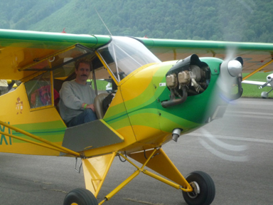
Here I am getting ready for the flight back. Kitfox Thomas hand propped the engine, as our L4 has no starter. It usually starts on the second or third try.
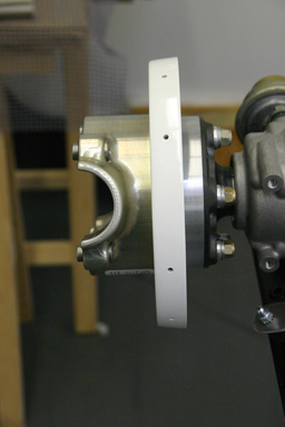
23.08.2009: Today I first finished installing the propeller.
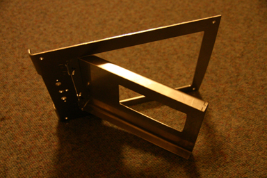
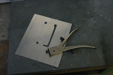
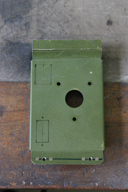
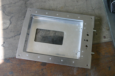
I then continued with the GPS mount. Here one of the pieces of aluminum, into which I had to cut a rectangular hole.
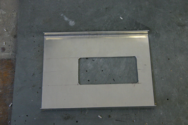
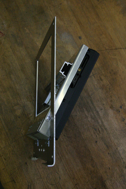
Below how the mount will work. The GPS is attached with a clip to the hat rail. To remove it I can tilt if forward to get access to the release handle. The tilting mechanism will be lockable so that it can’t be removed from the panel without the key.
26.08.2009: I continued with the panel today. First I had to add two holes for two more fuses to the right section of the panel, as well as a hole for the cabin heat activation cable. I put that one fully on the right side, as my passenger is normally the one which feels cold.
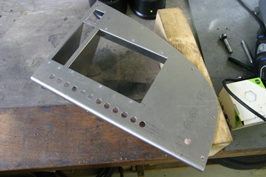
I then finished the centre section where the Garmin GNS430 NAV/COMM/GPS and the GTX330 Transponder will go. It finally turned out very sturdy, but I will non the less make a load test next week.
Then I built a pedestal underneath the front top of the fuselage, just behind the firewall, where normally the parachute goes if one is install. I decided against the parachute, however, as the plane is not an ultralight, but stressed to +4/-2 g. Instead I decided to use the space for the three (!) GPS antennas of my plane (GNS430, GPSMAP695 and FLARM). I made some tests to see whether the reception is good enough there by moving the fuselage outside, putting the GPS antennas there temporarily and checking signal reception on the GPS’s. From what I could see the reception is practically identical to putting the antenna outside on the fuselage, but it looks much nicer if they are not visible. If I ever detect problems with this installation I can still later mount the antennas on top of the fuselage. Unfortunately I did not take a picture, but I will do that later.
I then made the holes in the centre section next to the fuel valve where I will place the flap indicator and flap switch. I spent quite some time finding a location where
- I can easily reach the switch by just moving the hand off the throttle blindly without having to look for the switch
- I can see the indicator while having the hand on the switch
- I, or the passenger, won’t accidentally push on the switch while in cruise
Below one can see where I will put the switch (top) and the indicator (below).
Finally I added two aluminum angles to the GPS mount. They will allow me to eventually add a map tray behind the GPS, but also serve to install the lock.
I also wanted to bring the panel to the painter, but ran out of time, so I will have to find a slot next week to do that.
28.08.2009: I got an MMS today from Sandro, the other SportCruiser builder in Switzerland, with a picture of his just completed panel:
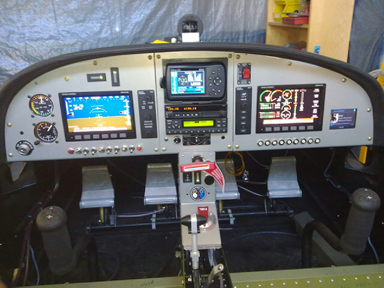
Cool, it seems he overtook us a bit.
I spent quite some time today with paperwork, as I want to have it ready when my plane is finished. Nothing more terrible than to have a plane that is ready but without the paperwork done.
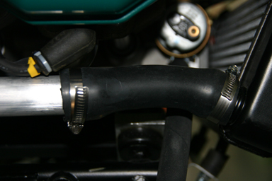
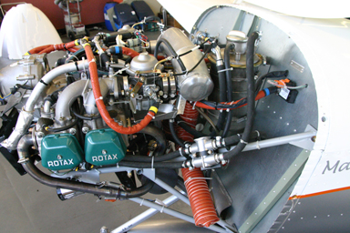
29.08.2009: Today we started “plumbing” the engine. The first item to be connected was the water cooler, which is connected to the water pump via two aluminum tubes. Both are attached to the cooler and the pump by using short sections of water hose, which are attached with hose clamps.
Today we had the Dutch registered SportCruiser (PH-URS), which is currently for maintenance at our airport, as reference. Even though the 100 hours check was finished on Friday, Silvan left the cowling open so we could check how things are done at the factory over the weekend.
We noticed that the factory uses another water cooler than we received with our kit. Ours is stock Rotax, but the one from the factory has edges which are tapered on the outer corners. We know that some planes had problems with the cowling touching the cooler, which can damage either due to vibrations. Below left the Rotax cooler, below right the one from CZAW.
As can be seen below the CZAW cooler (right) also has a water outlet that is pointing upwards, compared to the straight one at the standard cooler, which simplifies routing of the water line.
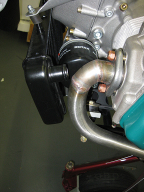
I will check with the factory whether the cowling has been enlarged on our plane or whether we got the wrong cooler. We could also always change it at a later stage.
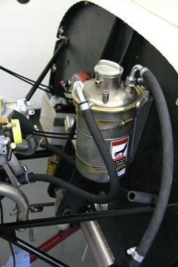
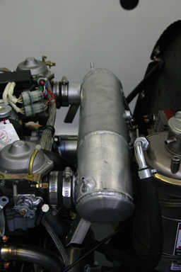
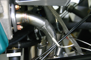
Next we continued with the oil system. The Rotax has an external oil reservoir. The engine oil flows from the bottom of the engine to the oil tank from there to the oil cooler and then back to the engine. Below we had to turn the oil outlet to face backwards so that the oil hose can run straight to the tank. At that moment we also drained the conservation oil from the engine.

Here the oil tank. The left hose is the one coming from the engine, the right one runs to the cooler.
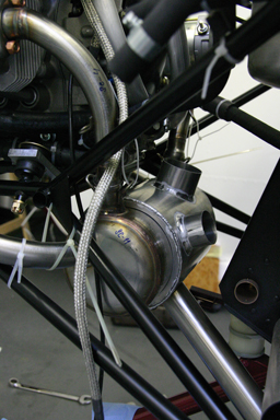
To better control the engine temperature we are installing an oil thermostat, as the one that can be seen on the picture below. It is taken from PH-URS. The thermostat is optional, and I ordered ours directly in Switzerland from the local Rotax representative. Unfortunately, however, it seems the thermostat was damaged during manufacturing. One of the threads into which a hose fitting is screwed is completely worn. I did not notice this when I received it, so I have to go and exchange it next week.
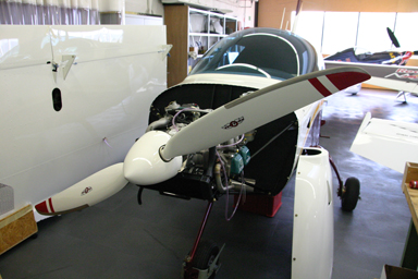
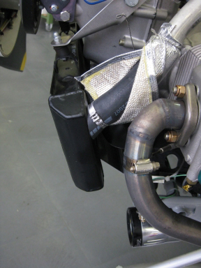
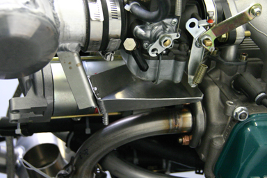
We continued with the exhaust system. There is a lot of space behind the engine, which makes installing it easy compared to e.g. the Kitfox of Thomas.
The exhaust is held in place with tie wraps during the installation. Once it has the right position the screws on the cylinder outlets are tightened and the tie wraps can be removed.
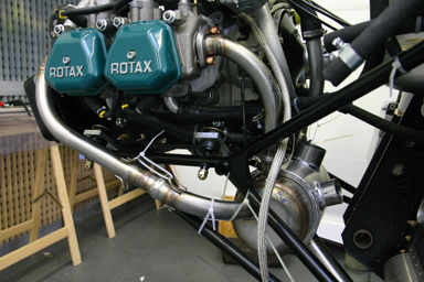
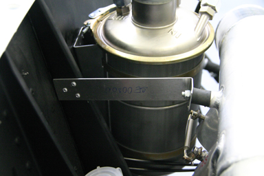
Next came the air box, which feeds cold or pre-heated air to the two carburettors. Again there is a lot of space, so it is easy to install just following the assembly manual.
It is also attached to the firewall with a small strip of aluminum and a rubber shock mount.
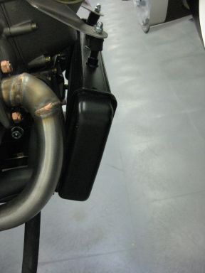
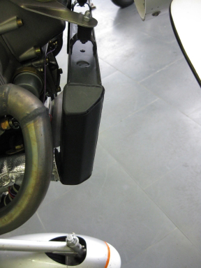
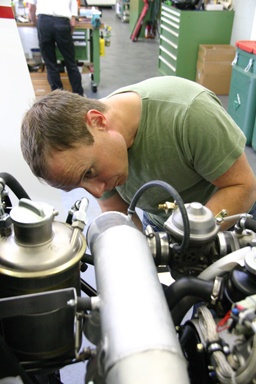
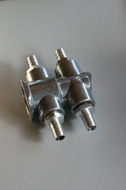
Below Rolf is installing the drip trays under the carburettors.
Here a picture of one of the drip trays. If a carburettor is flooded with fuel it flows out of the carburettor into the tray and from there through a tube out of the engine compartment.
Next we drilled the holes into the exhaust tubes for the exhaust gas temperature sensors. There are typically only two used on a Rotax engine. On PH-URS they are on the front left and rear right cylinder, even though the Dynon Engine Monitoring System installation manual specifies that they should be mounted both on either the front or the rear cylinders, with the rear ones the preferred location. We did as described in the manual and put them on the rear exhausts. Like that the exhaust gas temperatures should be more or less identical in normal operation. Any difference will indicate that one of the carburettors delivers a different amount of fuel than the other one.
Finally we wanted to start with the fuel lines, but we could not figure out how to install the vapour lock return line and where to put the fuel flow sensor. I will have to figure that out at home before continuing.
31.08.2009: Today I went to Aerotec in Grenchen, which is the Swiss importer for Rotax, to get an exchange thermostat for our faulty one. They just exchanged it without any formality, they did not even want to see the bill to prove that I bought it from them (which I did). I have to say I was surprised about that excellent service, big compliment.
In the evening I went to the airport to see whether the new one is ok, and it is. Here the thermostat with all the fittings installed. On the faulty unit one thread was damaged so much that the respective fitting could not be screwed in.
Today I also sent questions to Czech Sport Aircraft regarding the oil cooler and the fuel lines. I got a detailed response within about an hour, with a schematic showing the fuel system and a number of pictures. And they will also send me a water cooler with the new shape. Again excellent service, again big compliment.
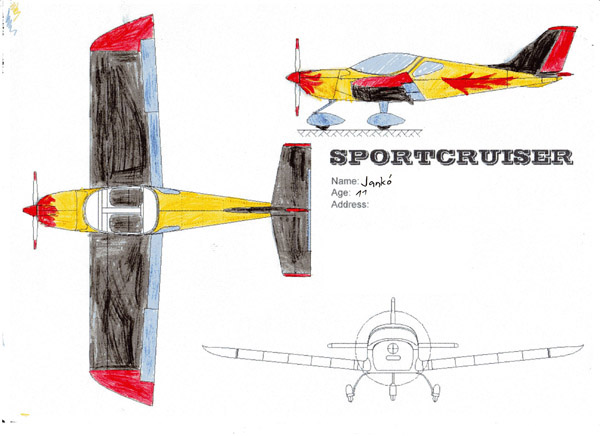
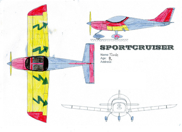
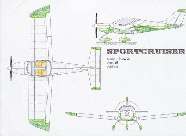
I finally also got to selecting a winners in the drawing contest I organised last year. Out of the entries I received the following ones take the first three places:
The Winner is: Jankó
The second place goes to: Tünde
And the third one goes to: Mélanie
Congratulations to the winners!
You will of course all get a free flight in the SportCruiser, once it is finished.