01.02.2009: I have updated the panel section to include the latest developments on the panel / avionics side.
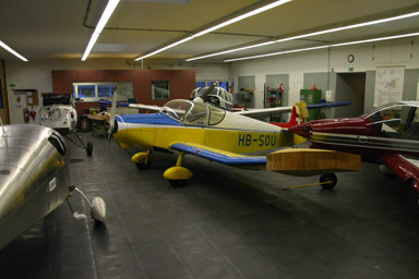
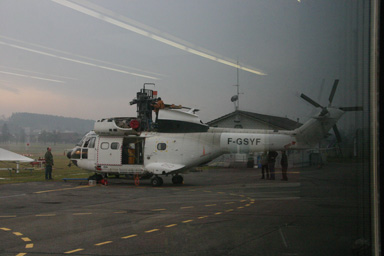
02.02.2009: Today we started our second building week. When I arrived at the airport the workshop was full with planes, as Kuerzi needed space in their workshop to paint one of the Aérospatiale Pumas they are working on, so we first had to move some of them out to make room..
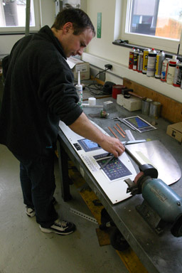
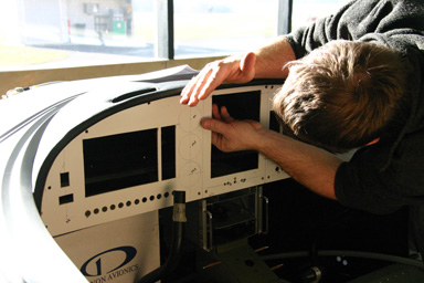
We then started with the panel. To be sure everything will fit we decided to make a wooden panel first, in which we can test fit all the instruments, before going after the “real thing”. To do that we used the one with the “paper” instruments I had produced earlier.
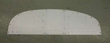
Here the result of our “design” effort. We had all real instruments at hand so we could take measure, which is better than relying on the data sheets.
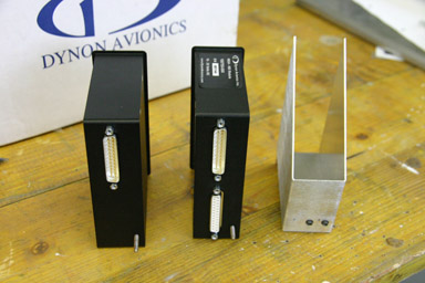
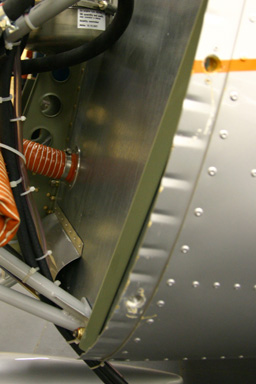
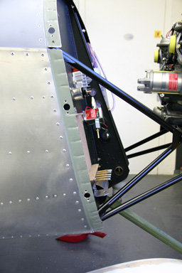
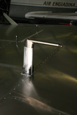
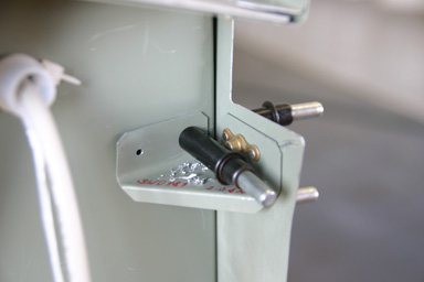
Rolf then started cutting the panel and I looked into a “problem” I discovered with the mounting tray of the Dynon EFIS Interface HS34 and the Autopilot AP74. Initially they had a kind of hook to install these units, but then they started supplying a new kind of mounting tray which better holds the units in the panel. We had one of each, which I did not like as I wanted to install both units in the same way. Sandro used the hooks for his panel so he gave me spare tray he had received with the Autopilot. I realised however that the HS34 would not fit as it has two connectors in the back instead of one, as the picture below shows.
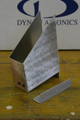
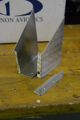
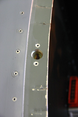
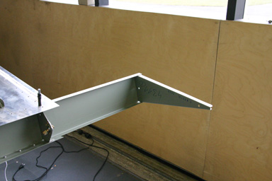
Rather than going back to using the hook I decided to cut the back so that I could also fit the HS 34 in it. Unfortunately one side is only bent from the back, so it falls off if you cut out the back wall to make room for the connector, as the pictures below show. I made a small angle to rivet the side to the bottom of the tray.
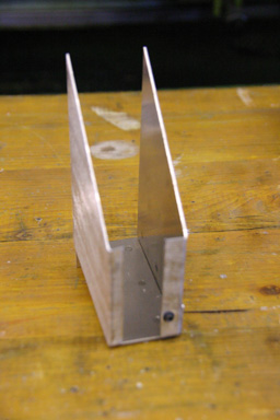
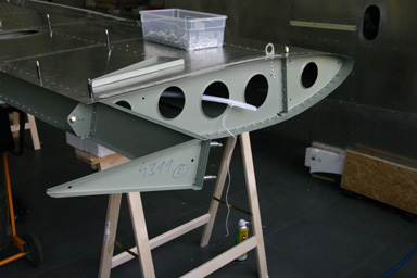
03.02.2009: Today I first finished the HS34 mounting tray pictured above. It now looks as follows:
Rolf continued with the panel mockup. It took him quite a while to cut out all the holes, but the result was a panel “just like a real thing”. This will help us to finalise the placement of all the instruments before cutting the aluminum panels.
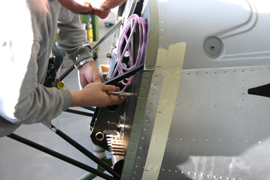
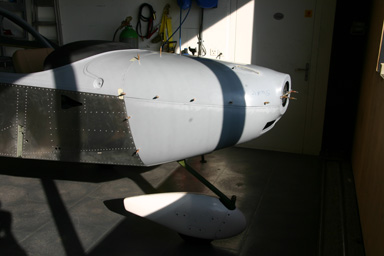
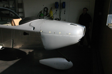
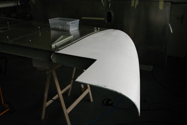
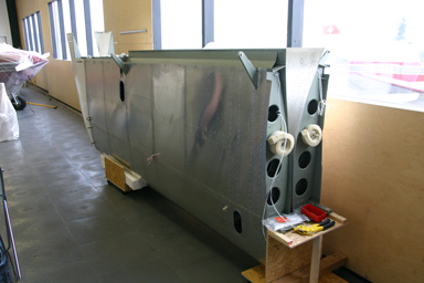
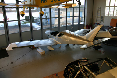
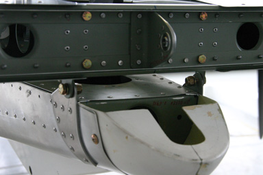
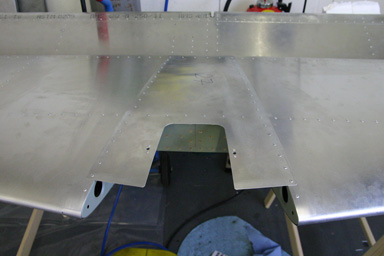
After that I continued with the cowling. Silvan brought us his self made pliers which can be used to dent the lip of the skin so that it bends inwards. Below a picture of the factory built plane, from which we realised why our cowling would not fit nicely.
Here a picture which shows how to make the dents. I first marked the places where the camlocks will go to leave the skin there straight.
I felt my hands afterwards…
That was however worth the effort, it really solved the problem. The cowling fitted nicely afterwards.
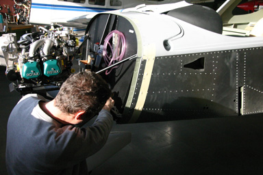
After that we drilled all the holes for the camlocks, both into the skin of the fuselage and in the cowling and started installing the camlocks to the fuselage.
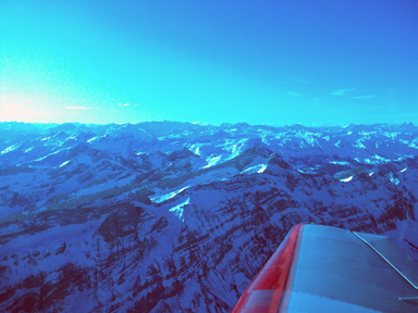
04.02.2009: The weather was too nice today to spend another full day in the workshop, so at 9 in the morning we took the Robin HB-KOF out for a little sightseeing over the mountains. The picture was made with the mobile phone, but it shows the view we had quite nicely.
After that we continued installing all the camlocks.
Here the result. The cowling now fits nicely.
The small stickers cover fur holes we drilled in the wrong place, we will close them with epoxy. Unfortunately the assembly manual and the drawings we got are describing two different versions of the cowling. Our kit came with the new version of the engine mount and cowling, but that manual describes the old one. In the new one some of the holes had to be shifted as the camlocks would interfere with the screw holding the engine mount.
In the afternoon we transported the wings to the airport. We initially planned to carry them on the roof of the car, but that did not work. Instead we went to a local car rental company which also rents out small trucks. That cost us around 80€, but saved the wings from getting damaged. Definitely worth the money.
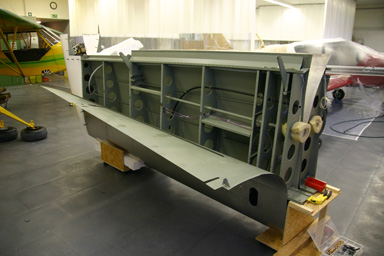
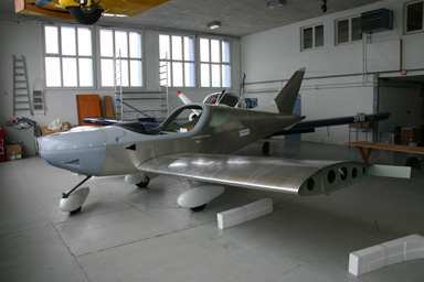
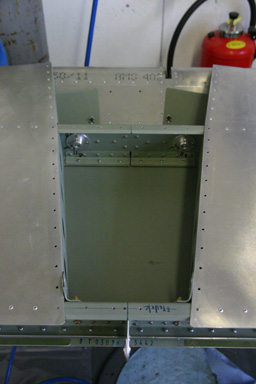
05.02.2009: We want to start painting the plane in about a month, so all work on the structure has for the time being priority. One of the open issues on the fuselage are the fairings between the fuselage and the wings, but they can only be fitted with the wings on the plane. That’s why we transported the wings to the airport yesterday.
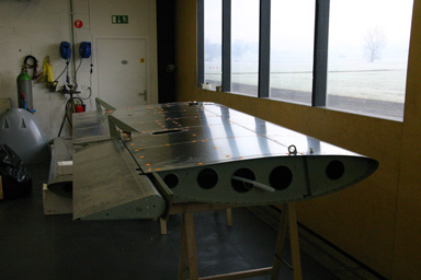
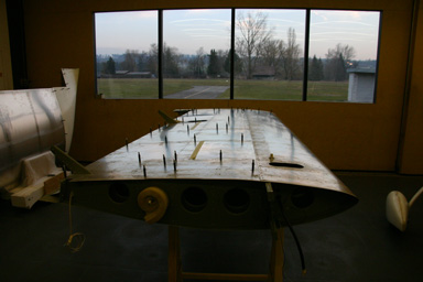
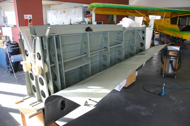
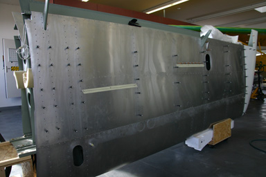
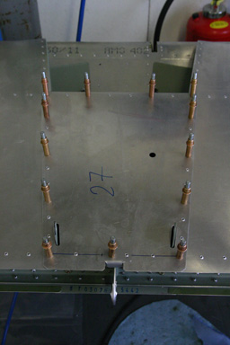
The wings come more or less pre-assembled. One large section of the skin is however only fixed temporarily. It has to be removed for the inspection of the wing interior and then riveted to the wing. We started drilling all the rivet holes to the correct size. After that we fixed the skin with clecos, so that we could drill out all the temporary rivets (marked with orange stickers on the picture above) and also drill these holes to the correct size. We then removed the skin to deburr everything. Next came vacuuming the interior of the wing, so that it can be closed. In the evening our building adviser came to inspect the wing, so we can start closing it tomorrow.
We did not make too much progress today, as Rolf had to go to the office in the morning and I spend some time working for the maintenance shop. In the afternoon we also helped Silvan to install a large curtain that creates a spray booth large enough for a plane, so that smaller paint jobs can be done in the workshop without having to fly the planes to a paintshop at another airport.
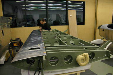
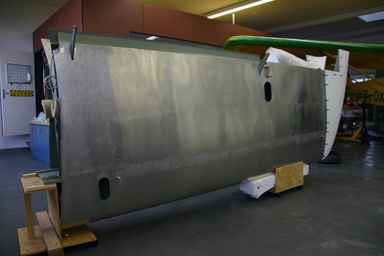
06.02.2009: Another day of preparing the wings for test fitting. We started by closing the first wing.
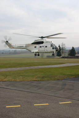
Looking out of the window we saw some other “kit-builders” installing the rotor-blades on a Puma helicopter which has been at Kuerzi avionics for quite a while for some avionics upgrades. According the the mechanics they will fly it to Basel, from where it will be flown to the US in an Antonov-124.
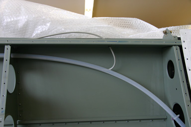
I did not let them distract me too much, so here the wing with the first two rows of rivets set. The skin can still be opened like that, as I still have to install the pitot including tubing and heating. On the right picture you see the pitot installed temporarily. Access to the interior will be impossible after closing the wing, so I am checking whether I can move the heater of the pitot tube to an accessible location. Different from most other SportCruiser we are installing a heatet pitot tube, which is required if ever we want to do night flying with the plane. It also has the advantage of supporting the angle of attack function of the Dynon EFIS, as it has two holes, one straight in front and one at an angled position. That will give us a stall warning function, which alone justifies the extra cost of the pitot tube compared to the standard one.

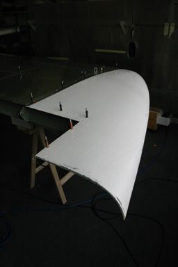
We then started installing the composite wing tip. There is just one rib necessary, which is riveted directly to the rear spar.
Here the view from the outside. The wing is laying on it’s back,
so the wing tip has to point downwards.
The tip is mounted with a row of A5 rivets on the top and bottom wing skins, as well as a row of rivets on the rear spar and the rib described above. The inner part of the rear edge has to be trimmed when installing the aileron.

The other guys were faster with their kit, they started hovering before we could finish the wing.
In the afternoon we repeated everything on the second wing full speed, and by 5 PM both wings had the same state. We can now install them one by one to fit the wing root fairing, but that will have to wait until the next building week. The wing on the left is stored in the wing holder, I will put the other one there too after the weekend to make room for aircraft maintenance.
07.02.2009: Today I first finished the second wing tip, as we did not have time yesterday to deburr and clean it correctly.
Then I looked at how to install the wings. CZAW recommends to use conically shaped rigging pins in their assembly instructions, as it is difficult to properly align the wing spars with the holes in the wing spar box without them. Here a picture of the rigging pins taken from the assembly manual.
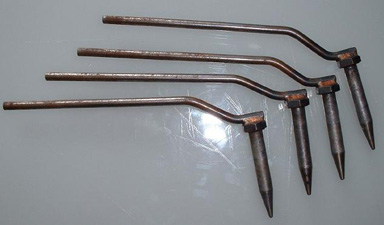
Wing rigging pins were not supplied with the kit so I decided to make some myself. I took AN bolts with the right diameter, polished them so that they would slide into the spar holes easily and made the front part conical. From the picture above I concluded that they made theirs in the same way. Next week I will ask someone in our factory to weld some handles to them as in the picture above.
20.02.2009: I do have to work once in a while, so no progress during the last two weeks. I did find out however during that time why I have this idea of an IFR certification (which is not practically possible based on Swiss regulations) in the back of my mind. During the last six days I had three out of my four airline flights cancelled, which means I spent many, many hours hanging around airport lounges. Worth mentioning that all the flights I was rebooked to were delayed between one and two hours… Wouldn’t it have been cool to just jump into my own plane? (Ok, even with IFR avionics it would not be good for flying in icing conditions).
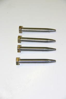
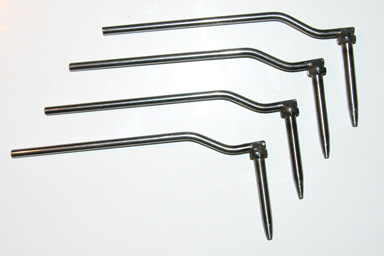
Today Rolf got the rigging pins back from the guysin our factory. The result is plain perfect, even better than the ones shown in the assembly manual (see above)… So we are ready to put the wings on next week to adjust the fairings and to rig the elevator.
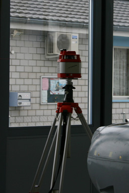
I also managed to borrow laser leveler from Urs, a fellow homebuilder, for the rigging of the wings next week. I got rigging instructions from CZAW, and with a laser reference this should not take more than a day.
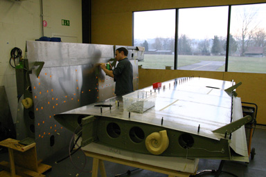
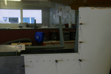
21.02.2009: Today I had a few hours at the airport, as I brought my daughter to her riding lesson not far from there and had to wait for the lesson to finish…. I used the time to permanently close the first one of the wings. The workshop is currently quite full, as two of the Robin DR-400’s are in the process of getting the wings painted in our newly installed painting booth, but the wings are in the wing stand where they do not take much room and for closing them it’s nearly easier when they remain in the wing stands than if they would lay flat. That is by the way also how they build them at the factory. The fuselage had to be moved to the hangar to make room.
First I opened the wing for a last inspection.
I ran the cable which will go to the aileron trim servo through the appropriate hole and checked everything else. The assembly manual contains a short checklist, which is quite handy.
I found two holes that we forgot to drill to full size, so I did that also.
Then I closed the skin with as many clecos as I could find and started riveting.
Below the result, after setting around five hundred rivets.
All in all this took me about three hours. On Monday I will close the second wing, which is a little more complex as it contains the pitot system. The wing tip is not yet installed permanently, as we first have to install the nav light and strobe.
23.02.2009: Today Rolf and I finishing the second wing. I started with opening the wing skin to finish the installation of the pitot system.
In parallel Rolf finished trimming the wing tips.
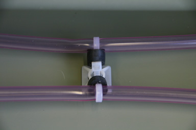
I had to secure the tubes running to the pitot. There are two tubes, as the Dynon pitot not only gives speed but also angle of attack information.
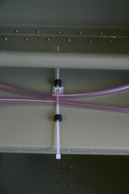
The tubes are fixed with cable binders as can be seen below.
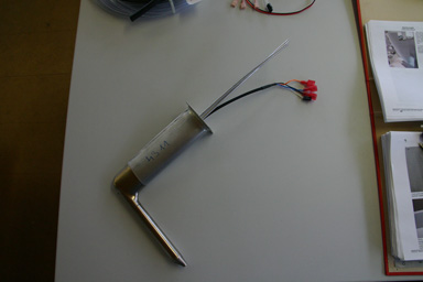
Here a picture of the pitot as it comes out of the box.
First I added some plastic tube to the two aluminum tubes, over which the pink tubes will be pulled.
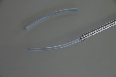
Below the result, it took quite some force to pull them over the aluminum tubes. I also had to bend the aluminum tubes, so that they do not touch the upper wing skin.
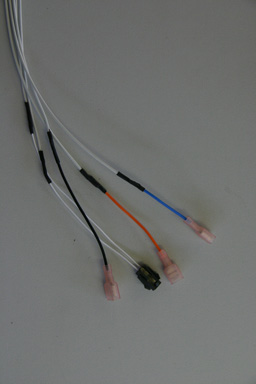
Next I had to extend the electric cable which runs to the pitot. As mentioned earlier we are installing a heated pitot, as I believe this will be necessary to get a night VFR certification. The pitot comes with a heater unit that has a thermostat built into. This not only reduces power consumption but also reduces the risk of burning out the pitot heater, as it needs to be heated with sufficient power for flying in cold air at full speed, which is of course too much power for standing still on the ground. The heater is normally installed quite close to the pitot, but that would require opening the wing if it ever needs to be repaired. I therefore decided to extend the cable so that I can install it in the fuselage. The Dynon installation manual specifies which cable cross section is required for such an installation, so I went over to Kuerzi to get the right cable.
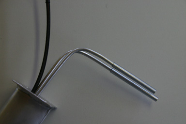
Here the pitot seen from inside the wing with the tubes not yet installed.
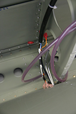
I ran the tubes and the cable out of the wing so that I can install the pitot after painting. This reduces the chance that we damage it during wing handling.
I spent the rest of the day closing the wing, which means another 500+ rivets…
Rolf in the meantime started with the landing lights, I will show pictures of them later. On Tuesday I will have to go to Paris on business, but Wednesday is another building day.
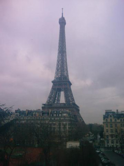
25.02.2009: Below a souvenir from my business trip to Paris. I don’t really like to go to Paris, as at least one of the transport modes I use to get there (plane, RER, Metro) is usually on strike, but I like the view from the meeting rooms at UIC.
Today we started assembling the plane! As I already mentioned the workshop is currently quite full, so we asked Kuerzi whether we can use their workshop for two days. We regularly help each other out, so this was no problem. Two weeks ago it would not have been possible however, as they still had the Puma helicopter in there, but luckily it is gone now.
It took us only a few minutes to attach the wings. It went smoothly as everything fitted nicely well and as we had prepared the rigging pins. It makes an unbelievable difference to see the fuselage with the wings attached, one really starts believing that the whole project will finally turn into a real plane.
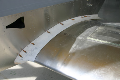
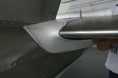
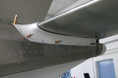
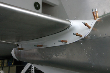
We immediately started fitting the composite wing fairings.
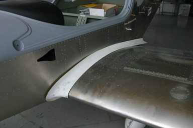
I marked the holes to be drilled based on photos I had made from the SportCruiser of Urs, as no drawings were supplied with the kit showing how they are attached. Due to the lack of drawings I asked CZAW how to do it and they told me to just start from the front and slowly work back to the end. Their advice worked and we had both fairings installed quickly.
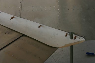
There is a small gap between the fairing and the flap, but I saw that this is also the case on the factory built planes.
In the meantime Rolf assembled our LED landing lights. Below a picture of the design we made. The upper part shows the three LED’s mounted on a piece of aluminum (for cooling), the lower part contains the reflectors. On the upper part the series resistors can also be seen, they are used to limit the current flow. We are using three Seoul Semiconductor Z7 Power LED’s in series. They have a forward voltage of 3.3 V at the nominal current of 1.4 A, which gives 9.9 V in total. We designed the resistor so that the nominal design current flows at the nominal battery voltage. We initially considered using a current regulating circuitry, but finally went for a simple resistor. The LED’s could actually be operated at 2.8 A, but only up to an ambient temperature of 30o, which we considered too low.
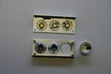
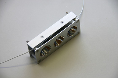
The whole thing is then assembled into a “sandwich”, in which the reflectors are pressed against the LED’s.
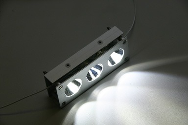
If you connect a battery the whole thing looks as on the picture below. We did some measurements earlier on to compare the LED’s with a 100 W GE-4700 landing light, but not yet with the finished assembly. I will publish the figures as soon as we have made additional measurements.
The standard GE-4700 landing light has a rated life of 25 hrs, according to the GE data sheet, the LED’s should have well above 10’000 hrs.
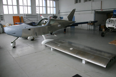
Later in the afternoon I started preparing the fairings of the horizontal stabilizer. Below a picture of the plane, ready for adjusting the inclination of the horizontal stabilizer, which we will do tomorrow.
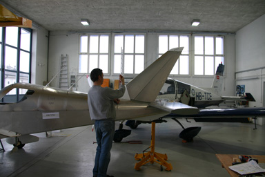
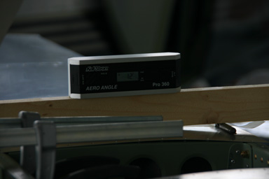
25.02.2009: Today’s plan was to rig the horizontal stabilizer. Instead of using “traditional” tool, such as spirit levels and wires we used a laser leveler that I borrowed from Urs, a fellow homebuilder. It is extremely easy to use, just set it up more ore less level on a tripod (there is a spirit level built into it to do that) and then switch it on. It then creates a laser beam that rotates in a completely level plane. As you can’t really see the laser beam in daylight it comes with a “receiver”, which you just hold into the beam and it then tells you whether it is too low, too high or precisely in the beam.
With this tool we managed to set up the plane according to the instructions we received from CZAW with little effort. To do that we used jacks borrowed from Silvan, both under the main gear and under the tail.
We then adjusted the stabilizer angle as instructed by CZAW to 1.2 degrees. The instructions were however not totally clear regarding whether the stabilizer is 1.2 degrees up or down, and to which reference the 1.2 degrees are measured, so I sent a mail to Tomáš Maršálek from CZAW and also called Graham Smith from Sprite Aviation in the UK. Graham really made a big effort to help and went to measure the angle on his SportCruiser, and Tomáš responded by mail within about two hours. Thanks to both, such excellent support is highly appreciated.
Drilling the two holes into the flanges was then a small thing, so the installation was finished shortly after lunch.
After that we also installed the fairings on the elevator. We had to trim them a bit, but again they went on easily.
The rest of the afternoon we looked into how to install the nav lights and strobes on the wing tips. We have not yet selected a solution, but have developed some nice ideas. The nav lights will consist of two red respectively green LED’s per side, and the strobes will be made with three LED’s per side to cover 120 degrees. The white light that points backwards as well as the backwards facing strobes can be installed in the wingtips as well. I checked the FAR 23 regulations, and they explicitly mention this possibility. Like that we won’t have to run an extra cable through the fuselage to the tail, where the rear facing light are normally installed.
26.02.2009: We finished the horizontal stabilizer today. We had to leave it open until now in order to be able to adjust the angle, but with that done yesterday we could close it.
On the upper surface a simple sheet has to be added, which will wrap around the base of the fin. We also added two anchor nuts, to which the stabilizer fairing will be attached. The fairing is riveted to the fuselage, but screws have to be used to attach it to the stabilizer so that the stabilizer can be removed if needed.
On the bottom of the stabilizer its the same game. There is also a small piece to be installed at the rear spar, as can be seen at the bottom of the right picture, which serves as elevator stop. I limits the elevator travel.
Here the finished product.

In the afternoon we built a prototype of the red navigation light. It uses two LED’s that together require 4 W instead of the 14 W of the bulbs which are normally used. It should give more than the legally required 40 Candela intensity in all directions, not only forward as specified in FAR 23.1391. I will publish pictures and additional information as soon as we have confirmed the intensity with measurements.
We also discussed again various possibilities how to install the nav lights, strobes and landing lights so that they are completely flush with the SportCruiser structure.
We had initially planned to spend the whole week building, but then I had to go to Paris on Monday and Tuesday. To compensate this we will continue building on Monday.