
08.02.2010: After a week abroad we could finally continue with the wiring today. The idea is to finish all wiring by the end of the week, lets see whether this proofs to be realistic.
First we had to redo all the sensor wiring forward of the firewall. The kit was delivered with firewall forward wires for all sensors, so we installed them last October. I then realised that the Dynon EMS came with a pre-made wiring harness, which meant that all wires would have to be spliced, if the already installed wires and the harness would be used. The harness looked to be a bigger job to do, so I undid the wires to the CHT, oil and fuel sensors and installed the ones from the harness instead.
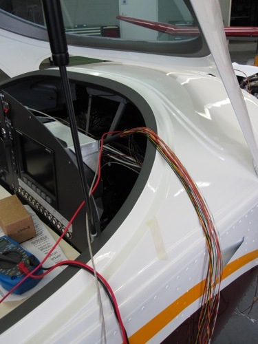
To do that we first connected the wiring harness to the instrument and then run the wires to the respective sensors, to make a nice cable loom. We let some slack in the harness, so that we can later tilt the panel forward if we have to access the wiring. The hole on top of the panel will later be closed by the instrument panel cover, making access difficult if the panel can not be tilted downwards.
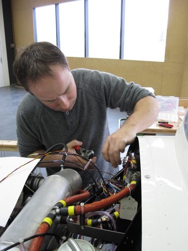
Here Rolf is installing some of the cable shoes.
It’s plain amazing how many cables are required even for such a small panel.
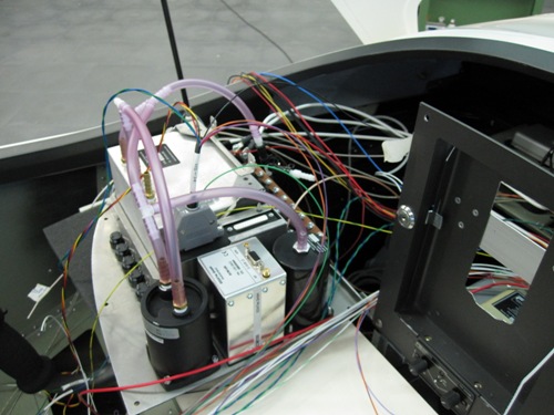
Here the part forward of the firewall, with the individual cables not yet nicely tied together.
I also found a nice video on Youtube about the PiperSport, which is the same plane as the SportCruiser but sold by Piper aircraft.
09.02.2010: We did more wiring today. I also managed to finish the schematics, after having solved the last questions by going over to Kuerzi Avionics for some advice.
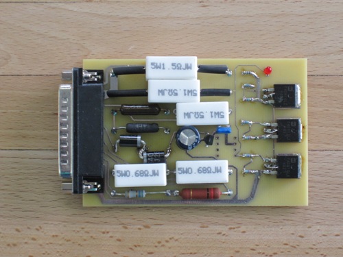
Rolf brought the electronics board today we did for the strobes. It contains the flasher circuitry as well as the series resistors for the NAV lights and the landing and taxi lights. We had to make it ourselves as all the lights, as well as the strobes, are self made with LED’s. The board is quite small compared to the standard Wheelen strobe unit (the connector on the left side is a 25 pin Sub-D connector), and also much cheaper than the Wheelen unit. The flashing sequence can be changed by reprogramming the PIC microprocessor on the board.
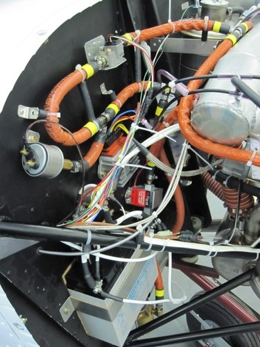
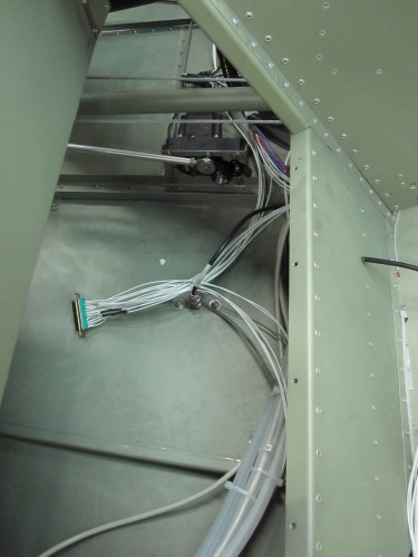
Below a picture from installing the wiring loom for all the lights. We will install the electronics board on the cabin floor behind the seats next to the autopilot servos.
10.2010: I spent again a few hours this afternoon working on the schematics.
11-12.02.2010: Two more days of wiring. To be honest, I spent only part of each day working on the plane, the rest was consumed by interruptions coming from my regular job as well as from issues from our flying club.
The worst part of the wiring is the outdated technology used on some of the devices, mostly the Garmin 430 and 330 units. The connectors are mounted in such a silly way that, once assembled it becomes a huge task to only add or remove a single wire. On the other hand it is impressive how few wires are requited thanks to connecting the
Garmin 430 and 330 as well as the Dynon with the ARINC bus interface. Here the result of wiring the two back plates of those units:
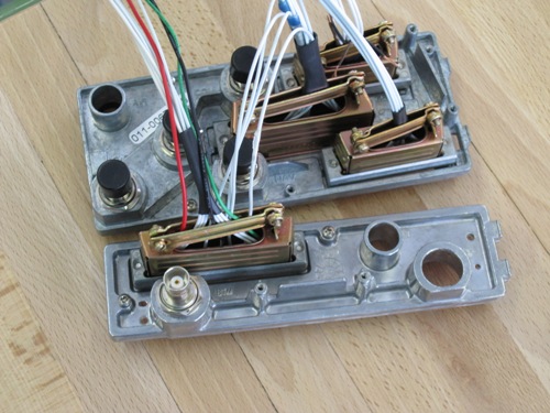
The back plates are then installed from behind onto the mounting trays.
Next week I will be off again, I hope however to finish the wiring in the following two weeks.