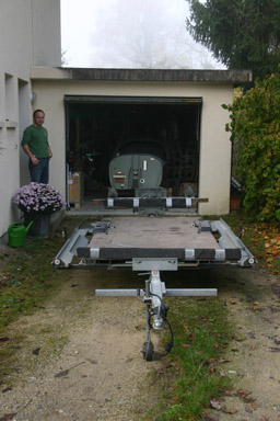
07.11.2008: Winter is slowly coming (we already had the first snow!) and building in the garage is getting kind of a cold affair. Luckily however I managed to get the permission to rent a corner of the maintenance workshop at our airport. Winter is less busy in the maintenance, so there is enough room to have the fuselage of our SportCruiser parked in a corner. I also managed to borrow a trailer which has been specially built to transport aircraft, so today we moved the fuselage from my garage to the airport. It is only a 12 km drive, which is quite convenient.
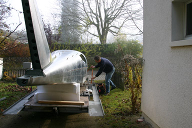
Luckily the fuselage without engine is not heavy, so we managed to lift it onto the trailer without problems.
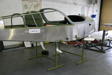
Here we are ready to move…
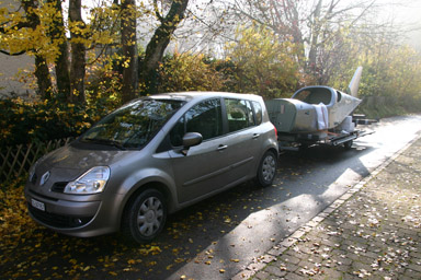
…and after 20 minutes (I drove quite slowly) at the airport.
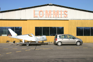
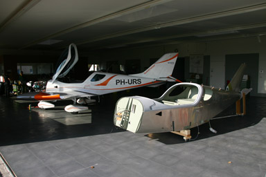
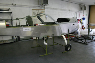
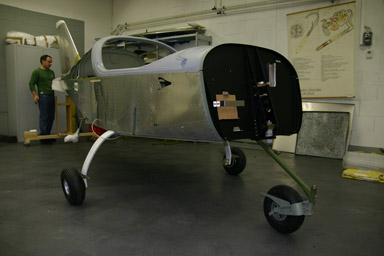
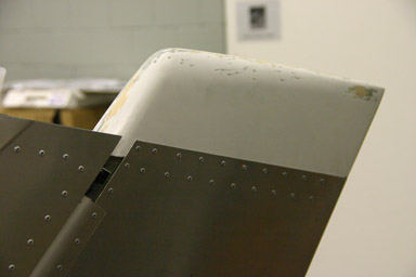
It was a pure coincidence that Urs was there with his SportCruiser for the 50 hrs inspection, so here a “before and after” picture. Still a long way to go until our plane looks like his…
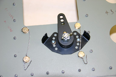
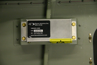
Rolf started preparing the gear as the next step will be to put the plane onto his own feet. I spent the time installing the remote compass module. We were wondering where to put it, but finally Sandro, the other builder, managed to get some pictures from the factory that show where they install it. It is in the back of the fuselage, so not visible in finished aircraft, but I could locate the rivets holding it on the plane of Urs.

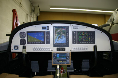
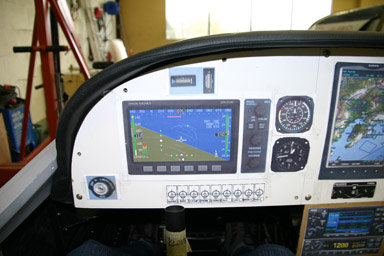
16.11.2008: Today I installed a mockup of my latest panel in the SportCruiser (it might not look like, but it’s just printed instruments fixed with scotch tape onto a piece of plywood). The biggest change on this latest edition of the panel is that I replaced the AvMAP IV GPS with the new GPSMAP 695/696 from Garmin. I currently fly with a Garmin 196, which has a small black and white screen, but non the less I am very happy with it. I always wanted a bigger color screen, and until a week ago the only reasonably priced unit available was the AvMAP IV. My panel was already nearly finished around that unit, but then Garmin announced the 695/696, the difference between the two is that the 696 comes with XM Weather and the 695 without. As XM Weather is not available in Europe I will go for the 695.
The only “problem” with the Garmin 695 is that it is made to be mounted vertically only, whilst the AvMAP can be mounted both vertically and horizontally. And with the Garmin 695 mounted vertically in the centre part of the panel there is no more room for the radio and transponder. I tried a number of arrangement, but the only practical ones are to install the radio and transponder in a widened centre post underneath the main panel, or to switch to the Becker radio and transponder, which would fit in the centre post without widening it.
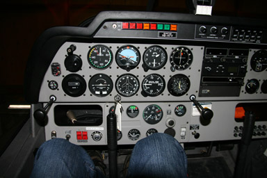
I wanted to check whether having the radio and transponder in the centre console would create problems, especially regarding leg room. I also wanted to check whether the throttle would be too close to the front of the radio and transponder and make it difficult to see / operate them.
My conclusion is that it is indeed a good possibility to mount the radio and transponder in a widened centre console, as there is still ample leg room (the radio will only be about 2.5 cm wider on each side than the standard console) and the vicinity of the throttle lever is no issue at all.
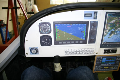
I did notice however that the Dynon EFIS is not straight in front of the stick but displaced by about 8 to 10 cm towards the centre of the plane. Remembering my flight instructor always saying “if you don’t sit straight you can’t fly straight” I went to check in the hangar what the panels of production aircraft look like. Here the result:
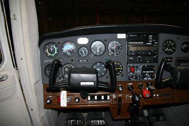
Robin DR-400: slight offset of the 6-pack to the right.
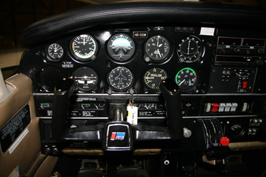
Cessna C-152: Instruments straight in front of yoke
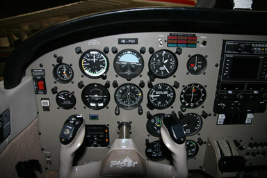
Piper Archer II: Instruments straight in front of yoke
Piper Archer III: Instruments straight in front of yoke
I posted a question on the Yahoo forum to see whether anybody has any experience with this or noticed the shift when flying his SportCruiser.
I then tried to shift the instruments so that the EFIS would be straight in front of the stick (that’s easy on a “paper” panel). Here two before / after pictures, I believe both versions are possible.
The resulting panel would then look like that:
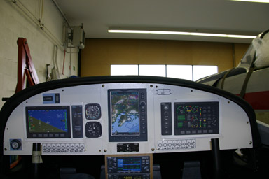
From the pilot’s point of view it would then look like that, which seems perfect to me:

To have done at least some “structural work” today I marked and pre-drilled the holes on the tail skid. This is the piece on the underside of the tail which protects the fuselage in case the tail strikes the ground. In addition there is a hole in it which can be used to tie down the tail during overnight parking.
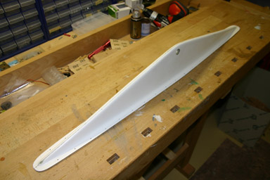
According to the plans there is one rivet every 50 mm, I guess that should be enough even for massive tail strikes.
22.11.2008: I have spent nearly the full week in Brussels, so no building. I did however finish the electrical schematics and I also ordered some of the missing material, including the OAT sensor for the Dynon and some sound proofing sheets. I have decided to sound proof the firewall (on the cockpit side) as well as the cabin back wall to reduce the noise inside the cabin. The bottom of the baggage area does not need sound proofing as it is carpeted, but the firewall and the back wall are just a bare sheets of stainless steel respectively aluminum. Sound proofing will add only a few hundred grams, which I think is worth trying it. The sound proofing material I ordered is fire retardant to FAA 25.853a, so no risk there.
I ordered the material from Sandelving Aviation Supply in Germany, which is a European representative of Aircraft Spruce. They carry the full assortment from Aircraft Spruce, even with the same part numbers. I have never ordered anything from them. but the shipping cost looks promising compared to when ordering from the US. I will report how well it worked.
Here what aileron the servo looks like installed in the servo mounting plate:
Today I found some time to start with the installation of the autopilot servos. I received additional drawings from CZAW, which helps a lot. The drawings are for the Digiflight servos, but as the ones from Dynon are mechanically interchangeable (not electrically!), so I can use the drawings without change.
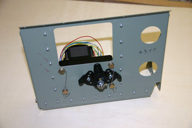
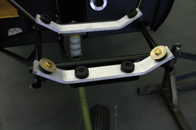
and here a more detailed look at the motion limiting bracket, which prevents the servo from going to 90 degrees and thus blocking the control system. The screws are secured with safety wire, these are the first ones I installed (but definitely not the last ones…).
The generic push rod kits that can be ordered from Dynon to link the servo with the planes control system can be used without change, the rods even have the proper length already.
27.11.2008: Today we worked the full day on the plane and made quite some progress.
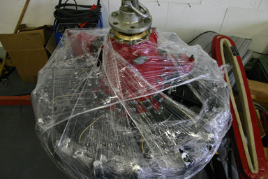
First we received our engine. It’s a Russian Vedeneyev M14P 9 cylinder radial with 400hp. I’m sure we will have the sportiest SportCruiser in the world…
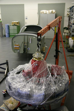
Unfortunately I’m just joking, the engine on the picture is a spare for a Yak-52 stationed at our airport.
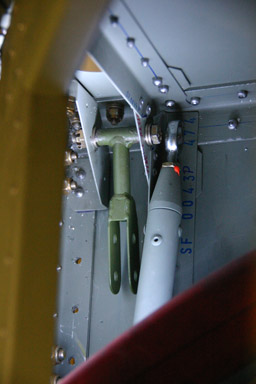
The first thing I started with this morning was to replace two arms of the aileron controls. They have been developed by CZAW to have a better control harmony between elevator and ailerons. The factory sends them to whoever wants them free of charge.
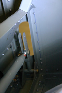
Above the old arm and below the new one. It took me about an hour and a half just to replace the two arms, as they are in a difficult to reach location. They are normally installed before the fuselage is finished.
After that we went to Kuerzi to order our avionics. Quite an expensive morning…
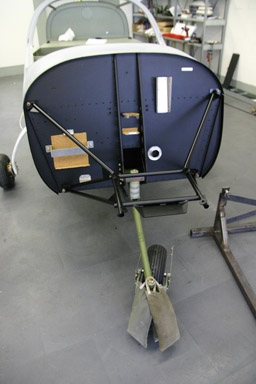
Then we installed the landing gear. First we put the fuselage on two stands to get enough clearance so that we could install the main gear.
Below the result.
When we wanted to start with the nose gear our mechanic told us that a firewall with primer on it is prone to corrosion, or at least does not look nice. I don’t know why it is primed in our kit, as the other fuselages I have seen have an unpainted, galvanized firewall, but we decided to paint it, which meant masking, cleaning and spray painting.
The paint was dry in an hour, which meant we could install the nose gear still before lunch. During lunch we discussed at which phase of the assembly we should paint the plane. After discussion various possibilities we concluded that it is better to paint it relatively early. We therefore decided that fitting fairings etc. should be given priority over installing the interior or the avionics.
One of the parts which requires work before painting is the cowling, as it has to be trimmed to fit. This is however only possible once the engine is installed, which requires the engine mount to be painted, so after lunch we brought the engine mount to a nearby paint shop. We can pick it up tomorrow morning!
Below the result of most of today’s work.
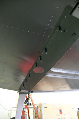
As I still had some time left I riveted the holder for the magnetic sensor of the Dynon into the aft fuselage.
Then I fitted the composite tip to the rudder. I will do the fin tomorrow, as it contains the NAV antenna. Installing the tip went smoothly, it’s just the normal drill – deburr – rivet sequence.
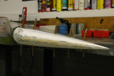
Here the result, it fits nicely.
28.11.2008: Another day of building and of good progress.
We started with installing the engine mount, which we could pick up from the painter this morning. Silvan then gave us some lead bags to hang onto the front wheel, so that the fuselage stays level on all three wheels and does no fall back onto the tail skid. This makes work much easier than always having to put a support underneath the tail.
We then started installing the aluminum bars which will fix the engine to the engine mount via rubber shock absorbers.
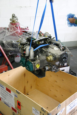
Next we unpacked the engine to fit it to the above supports.
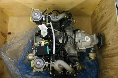
This would have been the last chance to install the 400 hp Vedeneyev M14P 9 cylinder radial, which was laying next to our Rotax 912 ULS, but we finally decided to stay modest.
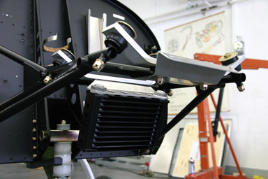
After mounting he oil cooler we wanted to install the Rotax, but then we realised that we did not have the two mounting bars required to hold the oil cooler in it’s place. I will have to see whether I have them at home, or whether they are missing in our kit.
As a result we put the Rotax back into the box…
and continued finishing the gear installation.
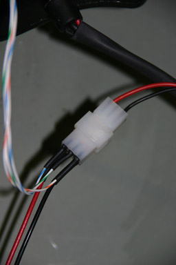
After that we started wiring the flap motor and flap position sensor. We decided to use Molex 1625 connectors throughout the plane, instead of the automotive style AMP Faston connectors foreseen for some of the wiring. The Molex connectors come in different pin numbers, are quite small and very lightweight, and are rated for 5 A each pin even under environmental conditions present in a plane.